
Thermal superconducting heat dissipating plate and finned heat sink

A thermal superconducting and heat-dissipating plate technology, applied in the field of heat transfer, can solve the problems of large temperature difference between the heat-dissipating plate and the heat-sink substrate, small heat-exchanging area of ​​the heat-transfer pipeline, burnout of the heating element, etc. The effect of reducing temperature difference and avoiding burnout

Pending Publication Date: 2019-07-02
ZHEJIANG JIAXI TECH CO LTD
View PDF0 Cites 3 Cited by
  • Summary
  • Abstract
  • Description
  • Claims
  • Application Information

AI Technical Summary

Problems solved by technology

However, the inner wall of the heat transfer pipeline in the heat dissipation plate of the prior art is generally smooth, the heat transfer area of ​​the heat transfer pipeline is small, the thermal resistance is large, and the heat transfer capacity is limited, so that the heat dissipation plate and the radiator substrate The temperature difference between them is large, even if the temperature difference between the cooling plate and the heating element is large, it is easy to cause the heating element to burn out

Method used


Image

  • Thermal superconducting heat dissipating plate and finned heat sink
  • Thermal superconducting heat dissipating plate and finned heat sink
  • Thermal superconducting heat dissipating plate and finned heat sink

Examples


Embodiment 1

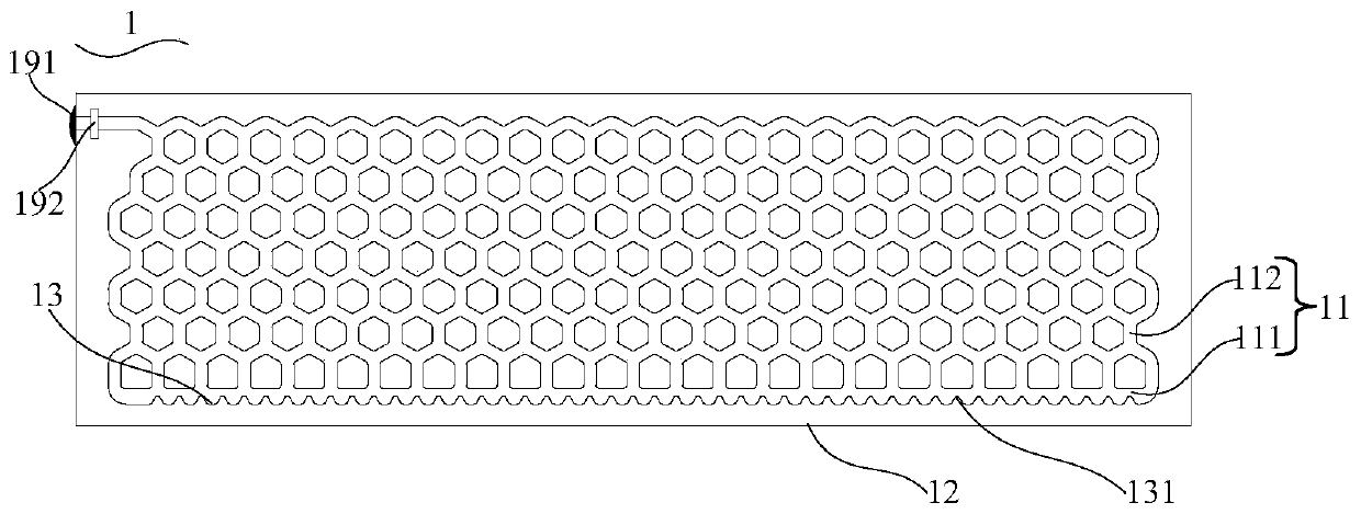
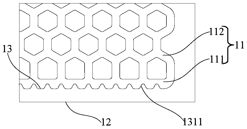
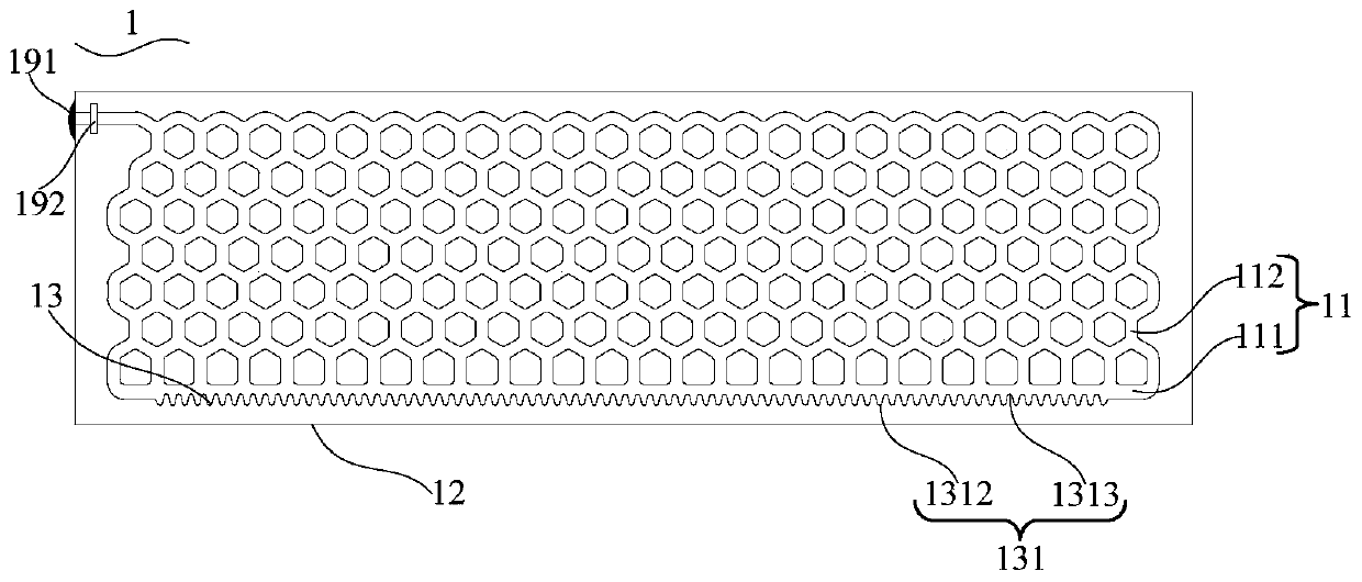
[0056] see Figure 1 to Figure 6 , the present invention provides a thermal superconducting cooling plate 1, the thermal superconducting cooling plate 1 is used to dissipate heat for heating elements such as electronic power devices, and a thermal superconducting circuit 11 is formed in the thermal superconducting cooling plate 1, so The thermal superconducting pipeline 11 is a closed pipeline, and the thermal superconducting pipeline 11 is filled with a heat transfer medium (not shown); the thermal superconducting pipeline 11 is provided with a heat transfer enhancing structure part 131, the The heat transfer enhancing structure part 131 is located on the inner wall of the thermal superconducting conduit 11 adjacent to the heating element, so as to increase the heat exchange area of ​​the thermal superconducting conduit 11 . Specifically, the heating element can be directly attached to the thermal superconducting heat dissipation plate 1, or can be attached to the surface of a...

Embodiment 2

[0071] Please combine Figure 1 to Figure 13 refer to Figure 14 to Figure 20 , the present invention also provides a finned radiator, the finned radiator comprising:

[0072] Radiator substrate 2;

[0073] Like the thermal superconducting heat dissipation plate 1 described in the first embodiment, the thermal superconducting heat dissipation plate 1 is arranged on the heat sink substrate 2 .

[0074] As an example, please refer to Embodiment 1 for the specific structure of the thermal superconducting heat sink 1 , which will not be repeated here. A heating element 3 is provided on the surface of the heat sink substrate 2 away from the thermal superconducting heat dissipation plate 1 , and the heating element 3 can be any power device capable of generating heat.

[0075] In one example, such as Figure 14 As shown, the thermal superconducting heat dissipation plate 1 can be directly attached to the heat sink substrate 2. Specifically, the thermal superconducting heat dissi...


PUM


Abstract

The invention provides a thermal superconducting heat dissipating plate and a finned heat sink. The thermal superconducting heat dissipating plate is used for dissipating heat of heating elements suchas a power device. A thermal superconducting pipeline is formed in the thermal superconducting heat dissipating plate, is a closed pipeline, is filled with a heat transfer working medium, and is provided therein with an enhanced heat transfer structure portion. The enhanced heat transfer structure portion is located on the inner wall of the thermal superconducting pipeline adjacent to a heating element to increase the heat exchange area of the thermal superconducting pipeline. The thermal superconducting heat dissipating plate can increase the heat exchange area between the thermal superconducting pipeline and the heating element and reduce thermal resistance by disposing the enhanced heat transfer structure portion on the inner wall of the thermal superconducting pipeline adjacent to theheating element, so that the heat transfer capability of the thermal superconducting heat dissipating plate is remarkably enhanced. When inserted into a heat sink substrate to which the heating element is attached, the thermal superconducting heat dissipating plate can reduce a temperature difference between the thermal superconducting heat dissipating plate and the heat sink substrate, namely the temperature difference between the thermal superconducting heat dissipating plate and the heating element, and improves the heat dissipation capability of the thermal superconducting heat dissipating plate.

Description

technical field [0001] The invention belongs to the technical field of heat transfer, and in particular relates to a thermal superconducting cooling plate and a fin radiator. Background technique [0002] With the rapid development of power electronics technology, the requirements for modularization, integration, lightweight, low cost and high reliability are getting higher and higher. Therefore, in solar inverters, uninterruptible power supplies (UPS), charging piles, power MosFET (metal oxide semiconductor field effect transistor), Diode (diode), IGBT ( Insulated Gate Bipolar Transistors) and other power devices. As the integration of these power components is getting higher and higher, the power density is also increasing, and the heat generated by themselves during work is also increasing. If the heat generated by the power devices cannot be dissipated in time and quickly, it will lead to power failure. The temperature of the chip in the device rises, which will cause ...

Claims


Application Information

Patent Timeline
IPC IPC(8): H01L23/367H01L23/427
CPCH01L23/3672H01L23/367H01L23/4275
Inventor 仝爱星曾巧孙会会林深
Owner ZHEJIANG JIAXI TECH CO LTD
Features
  • Generate Ideas
  • Intellectual Property
  • Life Sciences
  • Materials
  • Tech Scout
  • Unparalleled Data Quality
  • Higher Quality Content
  • 60% Fewer Hallucinations
Learn More