Supercharge Your Innovation With Domain-Expert AI Agents!

Method of controlling a vapor compression system during gas bypass valve failure

A technology of vapor compression and bypass valves, which is applied in the direction of gas cycle refrigerators, compressors, separation methods, etc., and can solve expensive and other problems

Active Publication Date: 2020-12-04
DANFOSS AS
View PDF6 Cites 0 Cited by
  • Summary
  • Abstract
  • Description
  • Claims
  • Application Information

AI Technical Summary

Problems solved by technology

This is highly undesirable and can be very expensive

Method used


Image

  • Method of controlling a vapor compression system during gas bypass valve failure
  • Method of controlling a vapor compression system during gas bypass valve failure
  • Method of controlling a vapor compression system during gas bypass valve failure

Examples


Embodiment Construction

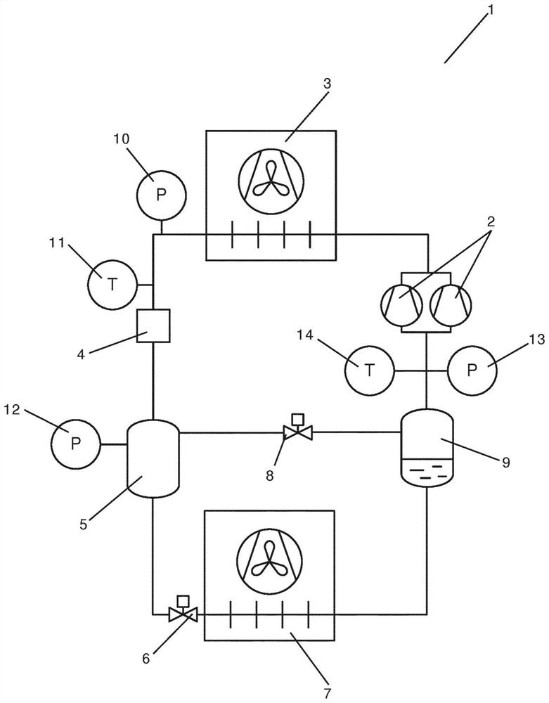
[0060] figure 1 is a simplified diagram of a vapor compression system 1 controlled using a method according to a first embodiment of the invention. A vapor compression system 1 comprises a compressor unit comprising a plurality of compressors 2 (two of which are shown) arranged in a refrigerant path, a heat rejection heat exchanger 3, a high pressure expansion device 4, a receiving 5, an evaporator expansion device 6 in the form of an expansion valve, an evaporator 7, a gas bypass valve 8, and a suction line receiver 9.

[0061] The refrigerant flowing in the refrigerant path is compressed by the compressor 2 and then supplied to the heat rejection heat exchanger 3 . In the heat rejection heat exchanger 3, heat exchange takes place with the auxiliary fluid flow 3 flowing through the heat rejection heat exchanger by removing heat from the refrigerant. In case the heat rejection heat exchanger 3 is in the form of a condenser, the refrigerant passing through the heat rejection ...


PUM


Abstract

A method for controlling a vapor compression system (1) is disclosed. Record gas bypass valve (8) failure. The actual opening of the gas bypass valve (8) and the target opening of the gas bypass valve (8) are derived based on one or more control parameters of the vapor compression system (1). comparing the actual opening with the target opening, and based on the comparison and for making the mass flow rate of the gaseous refrigerant passing through the gas bypass valve (8) and the actual opening of the gas bypass valve (8) The vapor compression system (1) is controlled accordingly.

Description

technical field [0001] The present invention relates to a method for controlling a vapor compression system such as a refrigeration system, a heat pump or an air conditioning system, wherein the vapor compression system is allowed to keep running in the event of a failure of a gas bypass valve which keeps the receiver The gas outlet of the compressor is interconnected with the inlet of the compressor. Background technique [0002] Vapor compression systems such as refrigeration systems, heat pumps or air conditioning systems are usually controlled to provide the required cooling or heating capacity in as energy efficient a manner as possible. Some vapor compression systems are provided with a receiver arranged downstream in the refrigerant path with respect to the outlet of the heat rejection heat exchanger and upstream with respect to an expansion device arranged to supply refrigerant to the evaporator. In the receiver, the refrigerant is separated into liquid refrigerant ...

Claims


Application Information

Patent Timeline
Patent Type & Authority Patents(China)
IPC IPC(8): F25B49/02F25B41/00
CPCF25B41/00F25B49/02F25B2341/0012F25B2400/075F25B2400/23F25B2500/19F25B2600/0253F25B2600/111F25B2600/2509F25B2600/2513F25B2700/1931F25B2700/195F25B2700/21152F25B2700/21163Y02B30/70F25B41/39B01D35/1475F25B1/10F25B49/022F25B2309/14F25B2700/193
Inventor 简·普林斯弗里德·施密特肯尼思·班克·马德森克里斯蒂安·弗里德施隆德
Owner DANFOSS AS
Features
  • R&D
  • Intellectual Property
  • Life Sciences
  • Materials
  • Tech Scout
  • Unparalleled Data Quality
  • Higher Quality Content
  • 60% Fewer Hallucinations
Learn More