Sand mold 3D printer

A 3D printer and sand mold technology, applied in the field of sand mold 3D printing, can solve the problems of low work efficiency, large space occupation, high labor intensity, etc., and achieve the effect of improving printing efficiency and reducing volume

Pending Publication Date: 2019-07-05
AMSKY TECHNOLOGY CO LTD
View PDF0 Cites 5 Cited by
  • Summary
  • Abstract
  • Description
  • Claims
  • Application Information

AI Technical Summary

Problems solved by technology

[0004] At present, the existing domestic 3D equipment adopts a single large-scale sand supply system, resulting in a large overall size of the 3D equipment. This large-scale

Method used


Image

  • Sand mold 3D printer
  • Sand mold 3D printer
  • Sand mold 3D printer

Examples


Example Embodiment

[0028] In order to further understand the content of the present invention, the present invention will be described in detail in conjunction with embodiments. The following embodiments are used to illustrate the present invention, but are not used to limit the scope of the present invention.
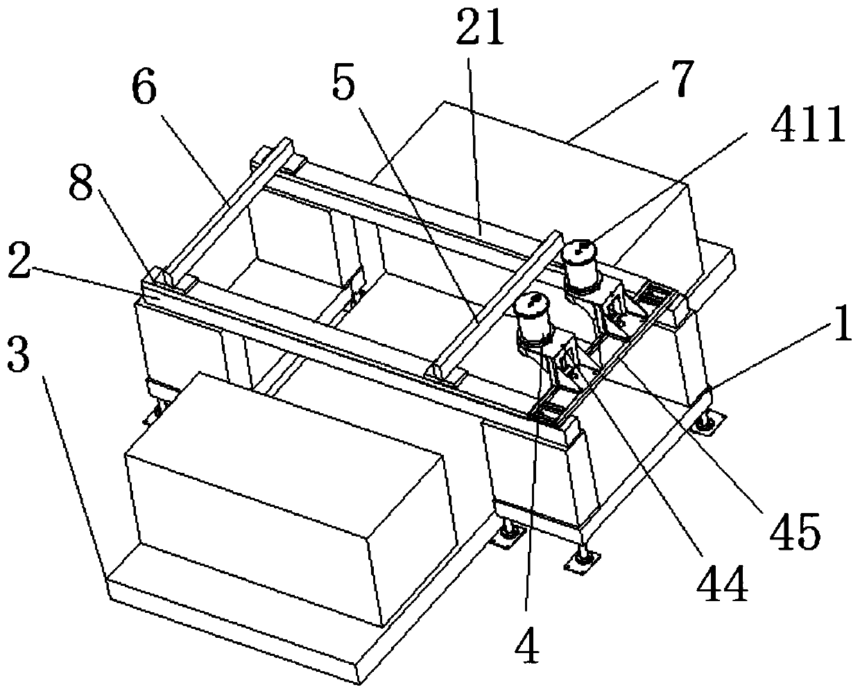
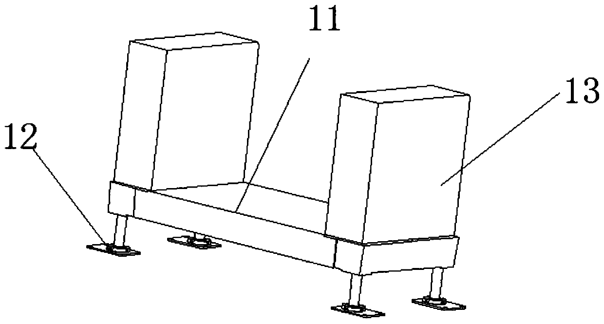
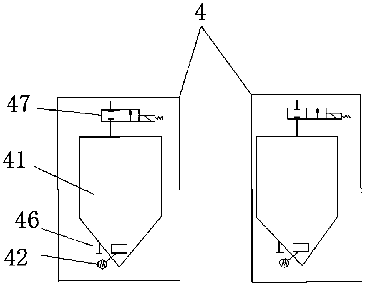
[0029] Such as figure 1 with figure 2 As shown, this embodiment relates to a sand 3D printer, which includes a printing base 1, a cross beam 2, a ground rail 3, a sand supply system 4, a sand spreading beam 5, a printing beam 6 and a working box 7; There are two or two beams 2 erected in parallel on the printing base 1, the ground rail 3 is set below the beam 2, the sand supply system 4 is fixed on the beam 2, the sand paving beam 5 and the printing beam 6 are erected at both ends On the beam 2 and slidably connected to the beam 2, the working box 7 is arranged on the ground rail 3 and is slidably connected to the ground rail 3. A lifting device for lifting the working box is also provided ...


PUM


Abstract

The invention discloses a sand mold 3D printer. The sand mold 3D printer comprises a printing base, cross beams, a ground rail, a sand supplying system, a sand paving beam, a printing beam and workingboxes, wherein the two cross beams are erected on the printing base in parallel, the ground rail is arranged below the cross beams, the sand supplying system is fixed on the cross beams, the two endsof the sand paving beam and the two ends of the printing beam are erected on the cross beams and are in sliding connection with the cross beams, and the working boxes is arranged on the ground rail and is in sliding connection with the ground rail. According to the sand mold 3D printer, the sand supplying system with two sand storage tanks is used for sand supplying, so that the size of equipmentcan be effectively reduced, continuous sand supplying can be ensured; the printing beam and the sand paving beam are driven by a linear motor, so that the operation stability of equipment can be improved, the noise is reduced, the two working boxes are adopted for printing, continuous work of equipment is realized, and the printing efficiency is improved.

Description

technical field [0001] The invention belongs to the technical field of sand mold 3D printing, and in particular relates to a sand mold 3D printer. Background technique [0002] 3D printing technology is also called rapid prototyping manufacturing technology. The basic principle is to repeatedly print a certain thickness of material on the platform, and repeat until the entire molded part is produced. Its process engineering is to use 3D modeling software to create a 3D solid shape, then discrete and layer the designed solid shape through the processing software of the rapid prototyping equipment, and then input the processed data into the equipment for manufacturing, and finally need to carry out certain Post-processing to get the final product. [0003] With the development of 3D printing technology today, its development focus has shifted from 3D printing prototypes to rapid manufacturing and rapid direct manufacturing of metal parts. 3D printing technology is not only ...

Claims


Application Information

Patent Timeline
IPC IPC(8): B22C9/02B33Y30/00
CPCB22C9/02B33Y30/00
Inventor 曹正文熊志越孙佳东练小金
Owner AMSKY TECHNOLOGY CO LTD
Why Eureka
Try Eureka