Numerical control gantry linear guide rail forming grinding machine

A linear guide rail and grinding machine technology, which is applied in the direction of grinding machines, grinding bed, grinding machine parts, etc., can solve the problems of affecting the service life of parts, low processing efficiency, and scratches of parts, so as to save costs and achieve good results , to ensure the effect of cleaning

Inactive Publication Date: 2019-07-05
南通瀚盛机床科技有限公司
View PDF5 Cites 7 Cited by
  • Summary
  • Abstract
  • Description
  • Claims
  • Application Information

AI Technical Summary

Problems solved by technology

[0003] The traditional CNC gantry grinder has the following problems: if the workpiece is relatively low, it is necessary to replace the worktable with a larger thickness, or to increase the height, which increases the cost; when processing a workpiece with a special surface, it can only be ground back and forth with a small contact surface , the processing efficiency is low; the floating debris generated by grinding is easy to enter the main shaft or the beam of the slider to cause scratches on the parts and affect the service life of the parts. Therefore, an improved technology is urgently needed to solve the existing problems in the existing technology. this question

Method used


Image

  • Numerical control gantry linear guide rail forming grinding machine
  • Numerical control gantry linear guide rail forming grinding machine
  • Numerical control gantry linear guide rail forming grinding machine

Examples


Embodiment Construction

[0041] The following will clearly and completely describe the technical solutions in the embodiments of the present invention with reference to the accompanying drawings in the embodiments of the present invention. Obviously, the described embodiments are only some, not all, embodiments of the present invention. Based on the embodiments of the present invention, all other embodiments obtained by persons of ordinary skill in the art without making creative efforts belong to the protection scope of the present invention.

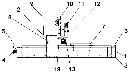
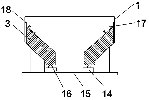
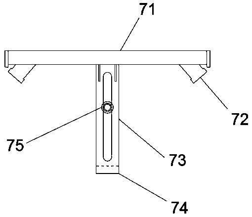
[0042] see figure 1 , the present invention provides a technical solution: a CNC gantry linear guide rail forming grinder, including a bed 1, a column 2, a lifting seat 3, a first motor 4, a steering gear box 5, a filament rod 6, a table mechanism 7, Dust removal mechanism 8, sliding seat beam 9, ram 10, slider mechanism 11, grinding head mechanism 12 and electrical controller 13, columns 2 are respectively arranged on both sides of bed 1, lifting seat 3 is ar...


PUM


Abstract

The invention discloses a numerical control gantry linear guide rail forming grinding machine. Stand columns are arranged on the two sides of a machine body, a lifting base is arranged in the machinebody, a first motor and a steering gear box are arranged at one end of the machine body, the first motor is connected with the steering gear box, the steering gear box is movably connected with a workbench mechanism through a long screw rod, and the workbench mechanism is movably connected with the lifting base. A dust removal mechanism is arranged in each stand column, an electrical controller isarranged inside any stand column through a telescopic rod, the upper surfaces of the stand columns are connected with the lower surfaces of sliding base crossbeams, and two rams are movably arrangedat one end of each sliding base crossbeam. Sliding block mechanisms are arranged at the ends, away from the sliding base crossbeams, of the rams. Grinding head mechanisms are arranged at the ends, away from the rams, of the sliding block mechanisms. The numerical control gantry linear guide rail forming grinding machine is reasonable in structure, there is no need to replace a workbench especiallyaccording to the height of a workpiece, the cost is saved, for bevel grinding, grinding can be conducted by rotating grinding heads, and the machining efficiency is greatly improved.

Description

technical field [0001] The invention relates to the technical field of numerically controlled gantry grinding machines, in particular to a numerically controlled gantry linear guide rail forming grinder. Background technique [0002] A CNC grinding machine is a machine tool that uses abrasive tools to grind the surface of a workpiece through numerical control technology. Most grinding machines use high-speed rotating grinding wheels for grinding, and a few use other abrasive tools such as oil stones and abrasive belts and free abrasives for processing, such as honing machines, superfinishing machine tools, abrasive belt grinders, grinding machines and polishing machine etc. CNC grinding machines include CNC surface grinders, CNC centerless grinders, CNC internal and external cylindrical grinders, CNC vertical universal grinders, CNC coordinate grinders, CNC forming grinders and so on. The grinding machine can process materials with higher hardness, such as hardened steel, ...

Claims


Application Information

Patent Timeline
Patent Type & Authority Applications(China)
IPC IPC(8): B24B27/00B24B41/02B24B55/06B24B55/00B24B47/12
CPCB24B27/0046B24B41/02B24B47/12B24B55/00B24B55/06
Inventor 钱兵吴晓军
Owner 南通瀚盛机床科技有限公司
Why Eureka
Try Eureka