Weaving machine tensioning mechanism

A technology of tensioning mechanism and weaving machine, applied in the direction of online netting, other household appliances, and conveying filamentous materials, etc., can solve the problems of complex mechanism, unfavorable equipment repair and maintenance, and inconvenience of production work, so as to achieve precise control and facilitate the later stage Maintenance and repair, the effect of convenient maintenance

Inactive Publication Date: 2019-07-05
肇庆市永智机械设备有限公司
View PDF1 Cites 0 Cited by
  • Summary
  • Abstract
  • Description
  • Claims
  • Application Information

AI Technical Summary

Problems solved by technology

However, the mechanism is too complicated, which is not conducive to the repair and maintenance of the equipment, and brings inconvenience to the post-production work.

Method used


Image

  • Weaving machine tensioning mechanism
  • Weaving machine tensioning mechanism
  • Weaving machine tensioning mechanism

Examples


Embodiment 1

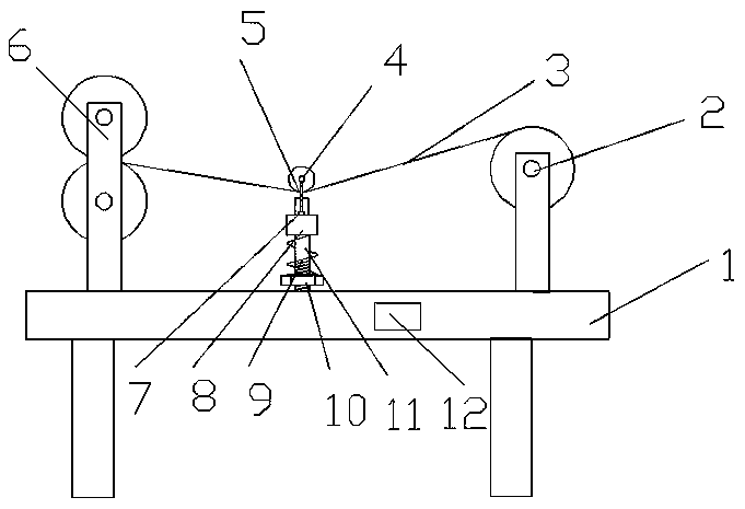
[0019] see Figure 1-2 , a braiding machine tensioning mechanism, including a table 1 and a driving device 6. The right end of the upper surface of the workbench 1 is rotatably connected with a bobbin 2, and the braided wire 3 to be braided is wound on the bobbin 2. The left end of the bobbin 2 is fixed with a vertical guide rod 11, and the guide rod 11 is nested Counterweight 8 is arranged, and counterweight 8 can slide on guide bar 11. The upper surface of the counterweight 8 is connected to the bottom of the connecting rod 5, the top of the connecting rod 5 is rotatably connected with the sliding wheel 4, and a tension sensor 7 is arranged between the bottom of the connecting rod 5 and the counterweight 8, and the tension sensor 7 can sense The tension between the counterweight 8 and the connecting rod 5. The lower end of the guide rod 11 is provided with a thread, and a nut 10 is nested on the thread, and a spring 9 is nested on the guide rod 11 between the nut 10 and th...

Embodiment 2

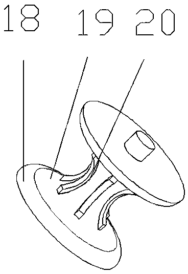
[0023] see image 3 , On the basis of Embodiment 1, the rotating roller 14 includes a crimp 18 and a plastic roller 19, the crimp 18 is symmetrically arranged on the outer end of the plastic roller 19, and the setting of the crimp 18 makes the braided wire 3 better enter the plastic roller 19 inside, to avoid derailment of braided wire 3. The side wall of plastic roller 19 is provided with some rubber teeth 20, and the setting of rubber teeth 20 has increased the frictional force between braided wire 3 and plastic roller 19, avoids the occurrence of slipping phenomenon in the transmission process, makes tightness adjustment more accurate.


PUM


Abstract

The invention relates to the technical field of weaving machines, in particular to a weaving machine tensioning mechanism. The weaving machine tensioning mechanism comprises a workbench and a drivingdevice, the right end of the upper surface of the workbench is rotationally connected with a wire winding barrel, weaving wires needing to be woven are wound around the wire winding barrel, and a vertical guiding rod is fixed to the left end of the wire winding barrel. A counterweight block is nested on the guiding rod, the upper surface of the counterweight block is connected to the bottom of a connecting rod, the top end of the connecting rod is rotationally connected with a sliding wheel, a tension sensor is arranged between the bottom of the connecting rod and the counterweight block, thedriving device is arranged at the left end of the guiding rod, a controller is mounted on the workbench, and the controller is electrically connected with the driving device and the tension sensor. The weaving machine tensioning mechanism has the advantages of being simple in structure, convenient to repair and maintain, precise in control and easy to implement and promote.

Description

technical field [0001] The invention relates to the technical field of knitting machines, in particular to a tensioning mechanism of a knitting machine. Background technique [0002] The shielded wire is a transmission line that uses a metal mesh braid to wrap the signal wire. The braid is usually red copper or tinned copper. The shielding layer of the shielding wire needs to be grounded, and external interference signals can be guided into the earth by this layer. In the weaving process of metal mesh, a weaving machine is needed. During the weaving process, the braiding machine needs to tension the braided wire to prevent the braided wire from loosening and causing loose filaments. However, the previous tensioning mechanism is relatively cumbersome and the equipment Maintenance will waste a lot of time, and the flatness of the braided wire cannot be guaranteed during the tensioning process, resulting in a significant decline in the aesthetics and quality of the finished pr...

Claims


Application Information

Patent Timeline
Patent Type & Authority Applications(China)
IPC IPC(8): B65H59/40B65H59/38B65H57/14B21F27/02
CPCB21F27/02B65H57/14B65H59/388B65H59/40B65H2701/36
Inventor 叶卫超陆思如
Owner 肇庆市永智机械设备有限公司
Why Eureka
Try Eureka