Device and method for improving oil field recovery efficiency

A recovery factor and oilfield technology, which is applied in the fields of production fluid, earthwork drilling, sustainable manufacturing/processing, etc., can solve the problems of ultra-low permeability reservoirs such as insufficient water injection, low formation pressure coefficient, inconvenient water intake, etc. , to achieve the effects of increasing oil recovery, reducing crude oil viscosity and improving mobility ratio

Pending Publication Date: 2019-07-05
XIAN CHANGQING TECH ENG +1
View PDF0 Cites 2 Cited by
  • Summary
  • Abstract
  • Description
  • Claims
  • Application Information

AI Technical Summary

Problems solved by technology

[0002] Under layered development, oilfields use water injection to maintain formation pressure. Generally, in order to improve oil recovery, oilfields re-inject treated water into formations. However, due to the low formation pressure coefficient, fracture development, and The salinity is high, the terrain is complex, and the ultra-low permeability reservoir is not injected enough water. At the same time, the oilfield is located in a remote area and water intake is inconvenient. Therefore, the existing water flooding method is not suitable for ultra-low permeability reservoirs. Oil field exploitation

Method used


Image

  • Device and method for improving oil field recovery efficiency
  • Device and method for improving oil field recovery efficiency
  • Device and method for improving oil field recovery efficiency

Examples


Embodiment 1

[0037] The first embodiment of the present invention relates to a device for enhancing oil recovery, such as figure 1 As shown, it is composed of three interconnected pipe networks, which are the injection pipe network, the liquid phase return pipe network and the gas phase vent pipe network;

[0038] The injection pipe network includes an injection pipeline 1, and the injection pipeline 1 is sequentially connected with a ball valve 1, a liquid feeding pump 3, a ball valve 4, an injection pump 5, a regulating valve 7, and a check valve in series from the inlet end to the outlet end. 8. The flow meter 9 and the regulating valve 2 17, the liquid carbon dioxide in the cryogenic storage tank is pumped into the injection pipe network from the inlet of the injection pipeline 1, and finally flows through the gas distribution valve group from the outlet of the injection pipeline 1 and injected into the ground;

[0039] The liquid phase return pipeline network includes a return line 10...

Embodiment 2

[0054] On the basis of Example 1, in addition to the injection pipeline 1, the injection pipeline network is sequentially connected with ball valve 1 2, liquid feeding pump 3, ball valve 2 4, injection pump 5, and regulating valve in series from the inlet end to the outlet end. 17. Check valve 8, flow meter 9 and regulating valve 2 17, the liquid carbon dioxide in the cryogenic storage tank 22 is pumped into the injection pipe network from the inlet of the injection pipeline 1, and finally flows through the gas distribution valve from the outlet of the injection pipeline 1 group injected into the ground;

[0055] Such as figure 1 As shown, the device for enhancing oil recovery also includes a branch line 2 16 as a bypass injection pipeline. The branch line 16 is connected in parallel with the injection pipeline 1. One end of the branch line 16 is connected to the outlet of the injection pump 5, and the other end is connected to the outlet of the injection pump 5. Regulate the...

Embodiment 3

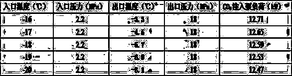
[0063] On the basis of Example 1, since the liquid carbon dioxide injected into the formation should be maintained at a low temperature and high pressure state, in order to observe the temperature and pressure of the liquid carbon dioxide in the pipeline in time, the inlet and outlet ends of the injection pipeline 1 are respectively equipped with temperature Gauge 20, pressure gauges 21 are respectively installed at the inlet port and the outlet port of the injection pump 5. If the temperature displayed by the thermometer 20 or the pressure displayed by the pressure gauge 21 is too low or too high, it can be adjusted in time through a valve or a pump, so as to avoid that the delivered liquid carbon dioxide does not meet the standard.


PUM


Abstract

The invention relates to a device and method for improving oil field recovery efficiency. A carbon dioxide oil displacement technology is applied to the development of tight oil, so that the oil displacement effect is improved, carbon dioxide can be well sealed underground, and the greenhouse gas effect in the atmosphere is reduced. The carbon dioxide can reduce the viscosity of crude oil, improvea mobility ratio, expand swept volume, and effectively solve development contradictions of ultra-low permeability reservoirs such as no water injection, insufficient water injection, difficulty in establishing an effective displacement system and channeling of injected water along fractures. The carbon dioxide and underground crude oil are mixed with each other (miscible), the characteristics oflow miscible pressure, low interfacial tension and the like are realized, on average, a recovery ratio of the oil field is increased by 5% to 15% on the basis of water flooding, and the oil displacement efficiency is improved.

Description

technical field [0001] The invention belongs to the technical field of oil field development, and in particular relates to a device and a method for improving oil recovery. Background technique [0002] Under layered development, oilfields use water injection to maintain formation pressure. Generally, in order to improve oil recovery, oilfields re-inject treated water into formations. However, due to the low formation pressure coefficient, fracture development, and The salinity is high, the terrain is complex, and the ultra-low permeability reservoir is not injected enough water. At the same time, the oilfield is located in a remote area and water intake is inconvenient. Therefore, the existing water flooding method is not suitable for ultra-low permeability reservoirs. Oil field extraction. Contents of the invention [0003] The purpose of the embodiments of the present invention is to provide a device and method for enhancing oil recovery, so as to overcome the above-me...

Claims


Application Information

Patent Timeline
Patent Type & Authority Applications(China)
IPC IPC(8): E21B43/16
CPCE21B43/164Y02P90/70
Inventor 王勇周子栋
Owner XIAN CHANGQING TECH ENG
Why Eureka
Try Eureka