Self-driven outer duct contrarotating annular fan blade compressing device

A technology of compression devices and external ducts, which is applied to jet propulsion devices, machines/engines, etc., can solve the problems of limiting the advantages of multi-ducted engine variable cycles, expanding the working range of engines, and limiting the choice of blade tangential speed, etc., to achieve increased The effect of design difficulty, structural layout optimization, and compact structure

Pending Publication Date: 2019-07-05
NORTHWESTERN POLYTECHNICAL UNIV
View PDF4 Cites 7 Cited by
  • Summary
  • Abstract
  • Description
  • Claims
  • Application Information

AI Technical Summary

Problems solved by technology

[0006] Due to the direct connection between the external ducted Flade blade tip fan and the internal ducted blades, it brings many disadvantages to the engine design: first, the design of the blade strength is difficult, which limits the selection of the tangential speed of the blade; second, the coupling connection makes the control The system is more complex, and the degree of freedom of adjustment becomes smaller, which is not conducive to the expansion of the engine's working range; thirdly, the performance of each duct cannot be taken into account, which greatly limits the multi-duct engine to take advantage of the variable cycle

Method used


Image

  • Self-driven outer duct contrarotating annular fan blade compressing device
  • Self-driven outer duct contrarotating annular fan blade compressing device
  • Self-driven outer duct contrarotating annular fan blade compressing device

Examples


Embodiment 1

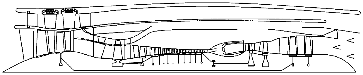
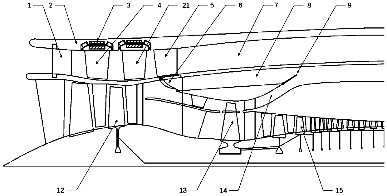
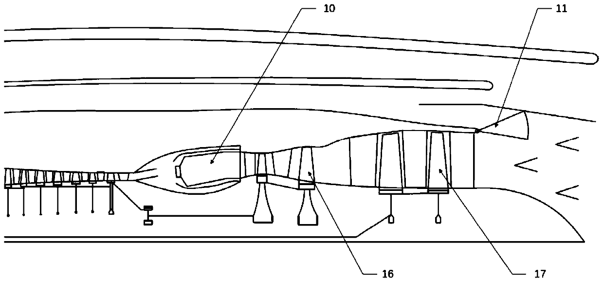
[0029] Embodiment 1: as figure 1 , figure 2 , image 3 , Figure 4 , Figure 5 As shown, a self-driven external duct annular counter-rotating fan blade compression device is provided with three flow channels inside, middle and outside at the rear of the traditional fan 12. The inside flow channel is connected with the core machine driving fan 13, and the middle flow The channel is connected with the entrance of the second outer duct 14, the outer flow channel is communicated with the entrance of the first outer duct 8, and the outlet of the second outer duct 14 is connected with the first duct ejector 9 through the front variable area. The outer duct 8 is connected, and a mode selection valve 6 is also provided at the entrance of the first outer duct 8; the rear part of the core machine driving fan 13 is the inner side and the outer side two annular flow channels, and the inner side The annular flow passage communicates with the high-pressure compressor 15, and the middle...

Embodiment 2

[0032] Embodiment 2: as Image 6 , Figure 7 As shown, it is the same as in Embodiment 1, except that the two rows of counter-rotating components include an upstream fan blade 4 and a downstream fan blade 21, and the upstream fan blade 4 and the downstream fan blade 21 are respectively arranged on two annular support frames. 18 on the outer wall, the annular support frame 18 has inner and outer walls, and an electromagnetic device 19 is arranged on the inner wall of the annular support frame 18; On the casing, the inner casing corresponding to the electromagnetic device is also provided with a motor stator 3, the magnetic poles of the electromagnetic device 19 and the motor stator 3 are arranged in a circumferential array, and the polarity of the electromagnetic device 19 and the motor stator 3 on the contrary. The bearing clearance of the slewing bearing is smaller than the blade tip clearance, and the blade tip clearance refers to the outer casing clearance between the fan...


PUM


Abstract

The invention relates to a device of adjusting bypass ratio of a turbofan engine continuously, in particular to a self-driven outer duct contrarotating annular fan blade compressing device. The self-driven outer duct contrarotating annular fan blade compressing device comprises an inner duct of the engine. A duct arranged on the outer side of the inner duct is a third outer duct, two rows of contrarotating members are arranged between an inlet guide vane and a stator vane in the third outer duct, the two rows of contrarotating members are separately upstream rotating members and downstream rotating members, and the upstream rotating members and downstream rotating members are arranged on a duct cartridge receiver of the third outer duct through a turntable bearing, separately. By adoptingthe two rows of contrarotating annular fan structures, the rotating speed of a rotor structure is reduced effectively and the dimension of the third outer duct is decreased effectively on the condition that the pressure ratio and the flow of the third outer duct are the same, so that the noise, the electric power consumption and the design difficulty are reduced, the working range of the turbofanengine is expanded greatly, and a variable cycle advantage of the engine is exerted to a greater extent.

Description

technical field [0001] The invention relates to a device for continuously adjusting the bypass ratio of a turbofan engine, in particular to a compression device for a counter-rotating fan ring of an outer bypass of a turbofan engine. Background technique [0002] A typical requirement of next-generation aviation gas turbofan engines is variable cycle. The variable cycle engine realizes the change of cycle parameters such as boost ratio, flow rate and bypass ratio by changing the geometric shape, size and position of some components, so that the engine has the best performance under various working conditions, so that the aircraft flight Altitude and Mach number, etc. have good adaptability. [0003] Thomas et al.’s U.S. patent US4043121, entitled “Double Rotor Variable Cycle Engine”, discloses an engine with a blade tip fan (Flade), which controls the air by adjusting the adjustable guide vane in the external duct of the blade tip fan. flow, enabling engine cycle variabili...

Claims


Application Information

Patent Timeline
Patent Type & Authority Applications(China)
IPC IPC(8): F02K3/072F02K3/077F02K3/075
CPCF02K3/072F02K3/077F02K3/075
Inventor 黄秀全王丁喜钱文韬曹东明
Owner NORTHWESTERN POLYTECHNICAL UNIV
Why Eureka
Try Eureka