Synchronous polarization phase shift focus measurement system based on Linnik type interference microscope

A technology of interference microscope and microscope objective lens, which is applied in the field of optical detection to achieve the effect of improving data processing speed, self-scanning speed and data processing speed.

Active Publication Date: 2019-07-05
NANJING UNIV OF SCI & TECH
View PDF9 Cites 13 Cited by
  • Summary
  • Abstract
  • Description
  • Claims
  • Application Information

AI Technical Summary

Problems solved by technology

[0008] The above methods mostly use the phenomenon and differential value on the detector to adjust the focus when in focus and defocus, but few methods give the focal plane to calculate the specific defocus amount

Method used


Image

  • Synchronous polarization phase shift focus measurement system based on Linnik type interference microscope
  • Synchronous polarization phase shift focus measurement system based on Linnik type interference microscope

Examples


Embodiment Construction

[0019] The present invention will be described in further detail below in conjunction with the accompanying drawings.

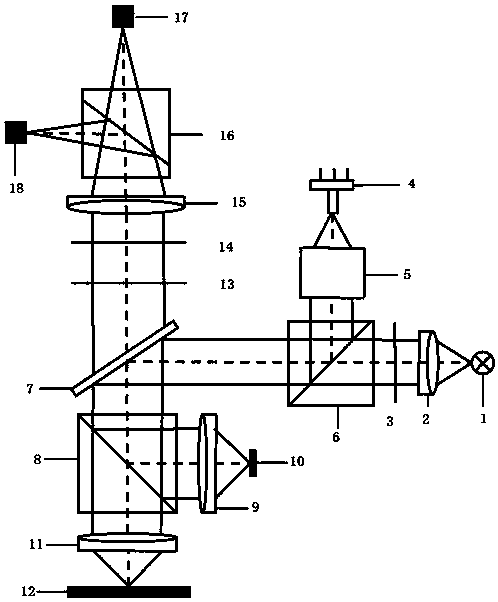
[0020] combine figure 1 , a synchronous polarization phase-shift focus detection system based on Linnik interference microscope, including white light source 1, collimator mirror 2, first 1 / 4 wave plate 3, laser light source 4, Kohler illumination system 5, polarizing prism 6, lens Mirror 7, cube beam splitter 8, first microscope objective lens 9, reference plane 10, second microscope objective lens 11, second 1 / 4 wave plate 13, analyzer 14, focusing lens 15, beam splitter prism 16, x Directional linear array CCD17, y-direction linear array CCD18; a total of the first optical axis set white light source 1, a collimator mirror 2, the first 1 / 4 wave plate 3, a polarizing prism 6 and a transflective mirror 7; a total of the second optical axis A laser light source 4, a Kohler illumination system 5, and a polarizing prism 6 are arranged in sequence; the sample t...


PUM


Abstract

The invention discloses a synchronous polarization phase shift focus measurement system based on a Linnik type interference microscope. The system comprises a white light source, a collimating mirror,a first quarter wave plate, a laser light source, a Kohler illumination system, a polarizing prism, a transflective mirror, a cubic beam splitting prism, two microscope objectives, a reference plane,a second quarter wave plate, an analyzer, a focusing lens, a beam splitting prism, an x-direction line array CCD and a y-direction line array CCD. The white light source generates white light, and plane polarized light is formed by means of collimation, polarization and the like. After being split by the cubic beam splitting prism, the light irradiates the reference plane and a tested sample through two microscope objectives. The return light is split by the beam splitting prism, and then irradiates the x-direction line array CCD and the y-direction line array CCD to generate an interference fringe image. Focus measurement is realized according to the defocus aberration change of the image. Laser is uniformly emitted by the Kohler illumination system, and is reflected by the polarizingprism and the like. The sample is directly written through the cubic beam splitting prism and the like. The system provided by the invention has the advantages of fast data processing and real-time focusing, and can acquire the position and shape information of the tested sample.

Description

technical field [0001] The invention belongs to the field of optical detection and specifically designs a synchronous polarization phase-shift focus detection system based on a Linnik type interference microscope. Background technique [0002] In terms of principle, autofocus can be divided into two categories: one is based on the distance measurement between the lens and the object to be photographed, and the other is based on the focus detection autofocus based on the clear image formed on the focusing screen. Autofocus technology implementation also has several different methods. [0003] The optical triangulation method proposed by F. Murakami et al. in the article "Accuracy assessment of a laser triangulation sensor", according to which the position of the imaging spot of the semiconductor laser on the position-sensitive detector will move accordingly when it is moved up and down by the side, through The triangle relationship can calculate the relationship between the ...

Claims


Application Information

Patent Timeline
Patent Type & Authority Applications(China)
IPC IPC(8): G01S17/08G01B11/24
CPCG01S17/08G01B11/2441
Inventor 高志山毕津慈于颢彪袁群孙一峰
Owner NANJING UNIV OF SCI & TECH
Why Eureka
Try Eureka