A rotor structure, electromagnetic bearing and electromagnetic loading device

A technology of rotor structure and electromagnetic bearing, which is applied in the direction of electromechanical devices, bearings, shafts and bearings, and can solve the problems of reduced precision of displacement test, unstable size, and decreased electromagnetic force

Active Publication Date: 2020-10-27
XI AN JIAOTONG UNIV
View PDF2 Cites 0 Cited by
  • Summary
  • Abstract
  • Description
  • Claims
  • Application Information

AI Technical Summary

Problems solved by technology

The electromagnetic properties of silicon steel sheets are good, but the dimensional stability of the material is poor, especially the axial dimension. It is formed by stacking multiple pieces of material, and the size is very unstable. The difference makes it difficult to guarantee the dimensional accuracy in the manufacturing process, so a larger dimensional tolerance has to be left in the design of the electromagnetic bearing, which sacrifices the comprehensive performance of the electromagnetic bearing to a certain extent, making it difficult for the electromagnetic bearing to achieve limited High performance at a smaller size
In addition, since the yield strength of silicon steel sheets is only 300-400MPa, solid materials have to be used instead of laminations at high speeds. Although it is easy to achieve high dimensional accuracy in processing, the electromagnetic properties of the materials are not very good. Once used Solid material, the eddy current loss of the rotor will increase greatly at high speed, and the eddy current loss will cause the electromagnetic force to drop rapidly with the increase of the rotor speed. Long-term loading will also cause serious thermal effects, and the heat caused will also cause rotor deformation. , Displacement test accuracy reduction and other issues

Method used


Image

  • A rotor structure, electromagnetic bearing and electromagnetic loading device
  • A rotor structure, electromagnetic bearing and electromagnetic loading device
  • A rotor structure, electromagnetic bearing and electromagnetic loading device

Examples


Embodiment Construction

[0033] The present invention will be described in further detail below in conjunction with the accompanying drawings and embodiments.

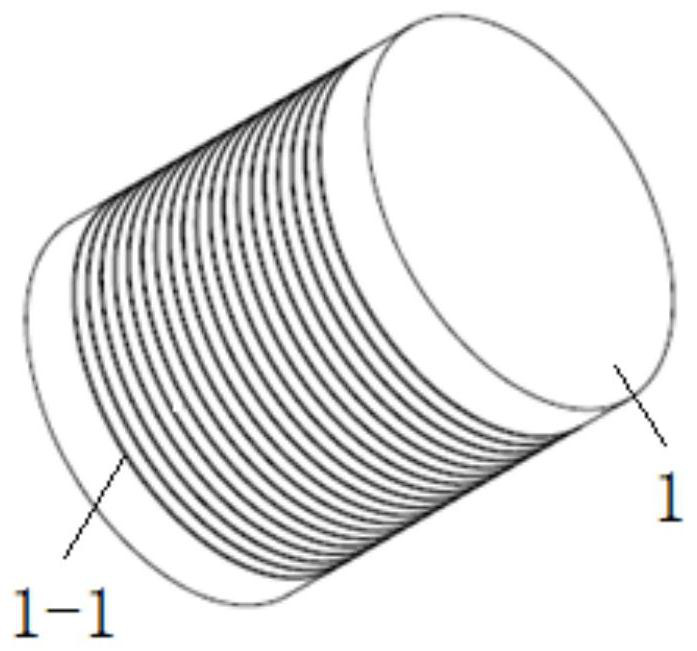
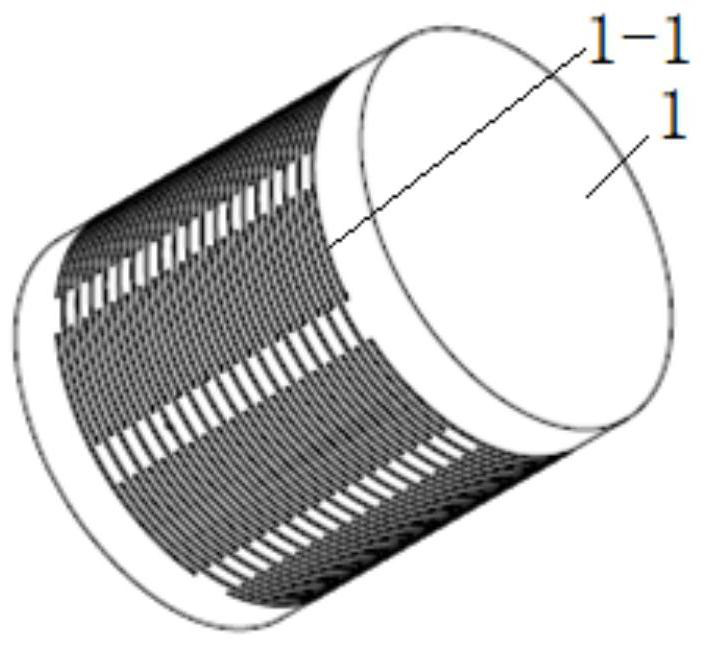
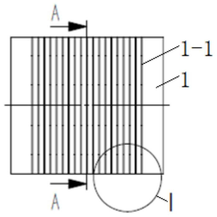
[0034] The technical principle of the rotor structure of the present invention is: when the solid rotor rotates in the magnetic field, the magnetic flux distribution inside the rotor is uneven, so that the magnetic flux is mainly concentrated on the surface of the rotor, and the eddy current is mainly concentrated on the shallow layer of the rotor. The closer to the rotor surface, the current The greater the density, the less current actually flows inside the rotor. The invention evenly cuts grooves on the cylindrical surface of the solid rotor, uses narrow and dense cut grooves to cut off the annular eddy current, limits the eddy current within a limited range, and greatly reduces the eddy current loss due to the high resistance of the circuit and greatly weakens the eddy current.

[0035] refer to figure 1 and figure 2 , the rotor structu...


PUM


Abstract

The invention belongs to the technical field of electromagnetic bearing and electromagnetic loading, and particularly relates to a rotor structure, an electromagnetic bearing and an electromagnetic loading device. A plurality of slots are disposed at the part of the body of the rotor structure passing through a magnetic field, and are uniformly arranged along the axial direction of the rotor structure. Each slot is disposed along the circumferential direction of the rotor structure. In the electromagnetic bearing, the journal of the electromagnetic bearing uses the above rotor structure. In the electromagnetic loading device, the loading test rod of the electromagnetic loading device uses the above rotor structure. The rotor of the invention has high dimensional accuracy and high overall strength, and can maintain a high load carrying capacity at a high rotational speed.

Description

technical field [0001] The invention belongs to the technical field of electromagnetic bearings and electromagnetic loading, and specifically relates to a rotor structure, an electromagnetic bearing and an electromagnetic loading device. The rotor structure of the invention is a low eddy current loss electromagnetic bearing and electromagnetic loading rotor structure suitable for high speed. Background technique [0002] The electromagnetic bearing is a non-contact bearing supported by magnetic suspension, which relies on the electromagnetic force generated by the controllable electromagnetic stator core with electromagnetic coils to suspend the rotor. It has the advantages of high application limit speed, no lubrication, small frictional resistance, high reliability, adjustable and controllable support stiffness, etc. Electromagnetic loading technology is a non-contact loading technology, which is developed based on the theory of electromagnetic bearings, and uses electroma...

Claims


Application Information

Patent Timeline
Patent Type & Authority Patents(China)
IPC IPC(8): H02K1/26F16C32/04
CPCF16C32/0468F16C2300/22H02K1/265H02K2213/03
Inventor 奚延辉张云飞王小鹏陈天宁
Owner XI AN JIAOTONG UNIV
Why Eureka
Try Eureka