
DCDC primary side feedback voltage detection setting circuit and method

A technology of voltage detection and primary-side feedback, which is applied in the directions of only measuring voltage, measuring current/voltage, and measuring electricity, etc., which can solve the problems of increased sampling power consumption, large RC delay, and high adjustment cost, so as to avoid no-load drifting High, small parasitic capacitance, fast sampling effect

Pending Publication Date: 2019-07-05
苏州源特半导体科技有限公司
View PDF0 Cites 4 Cited by
  • Summary
  • Abstract
  • Description
  • Claims
  • Application Information

AI Technical Summary

Problems solved by technology

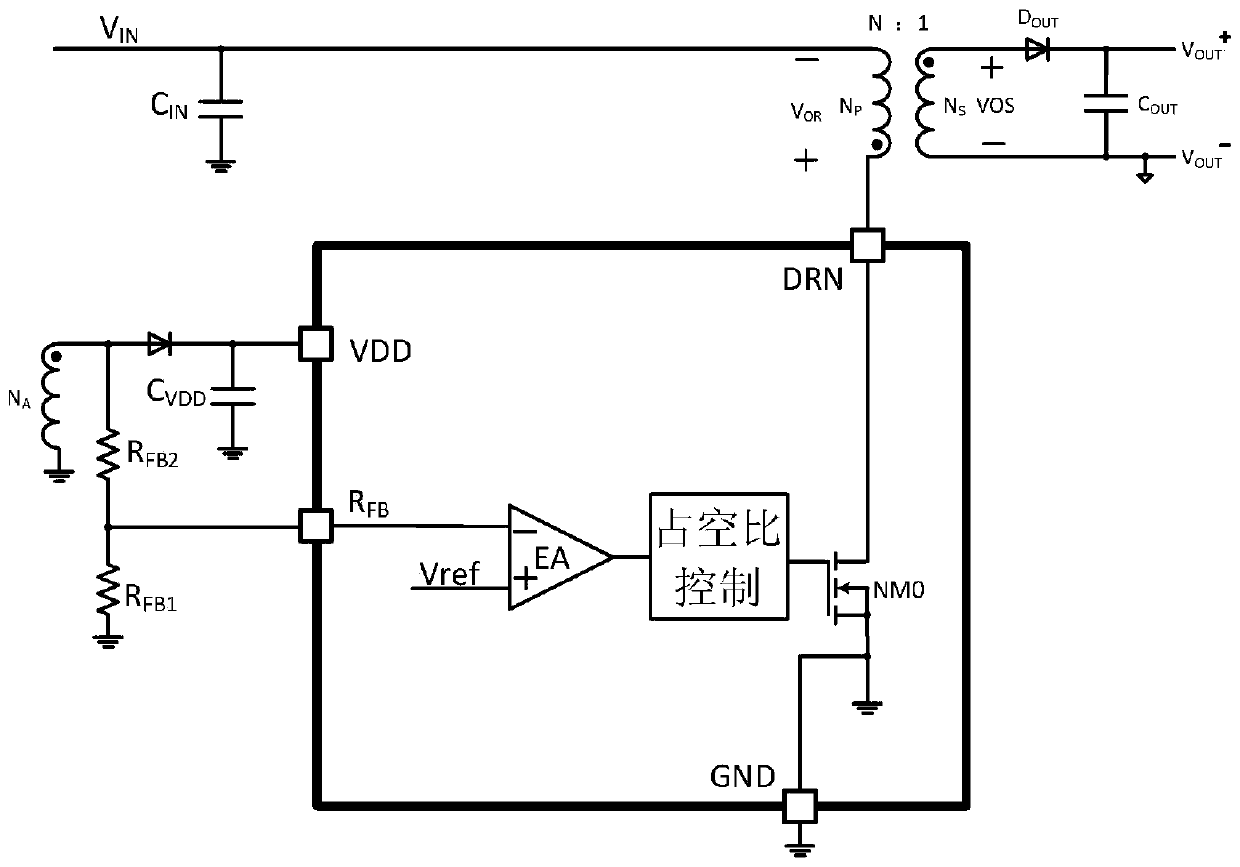
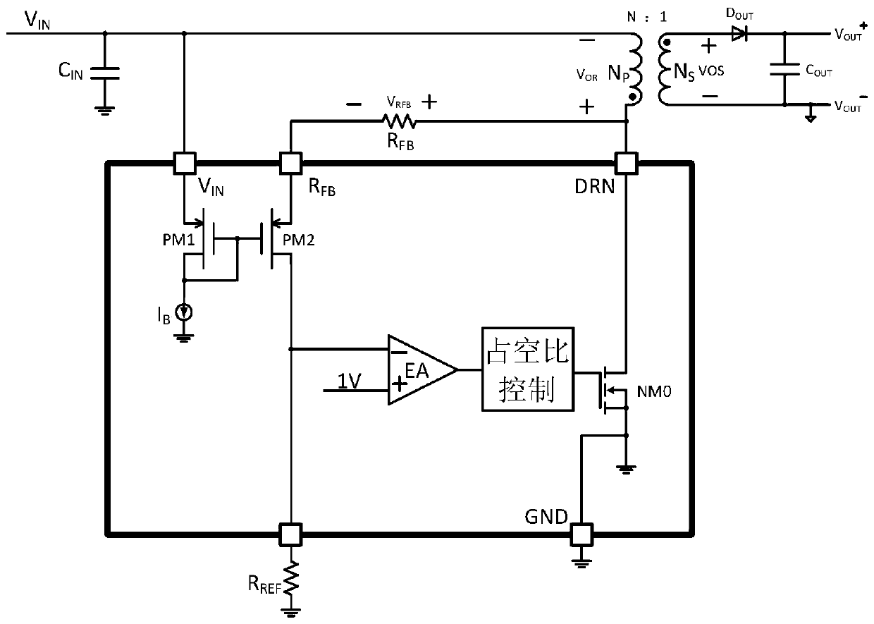
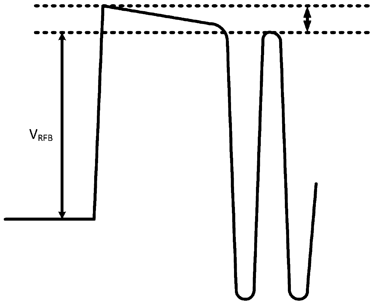
[0009] It can be seen that by setting the resistor R FB and R REF The size of the switching power supply can set the size of the output voltage, but this resistance R REF Generating the degaussing waveform of the winding to sample has a big defect at very light load: First, because the pin R REF There will always be parasitic capacitance at the place, especially sometimes in order to increase the anti-interference ability or the stability of the loop, if the capacitance is connected in parallel here, there will be RC delay, which will easily cause waveform distortion at high frequencies, especially at very light loads When the degaussing time is very short, the final detected waveform is not the ideal waveform that truly reflects the output voltage, and the actual sampled voltage is lower than the ideal, which will cause the output voltage of the switching power supply to fluctuate. The required power consumption and the anti-interference performance of the signal are not easy to compromise. If R REF The design is smaller and has the excellent characteristics of small RC delay and strong anti-interference ability, but this will obviously increase the sampling power consumption and the design difficulty of the differential sampling circuit. If the R REF The design is larger and the power consumption is lower, but the RC delay is large and the anti-interference ability becomes worse
However, this method has caused the problem of poor accuracy of the output voltage, because it is difficult to control the implanted concentration of ions in the integrated circuit and it is difficult to make the accuracy of the resistance accurate. The accuracy is generally outside ±15%, which directly leads to the output voltage The accuracy becomes worse
Of course, the resistance can also be corrected by means of electrical trimming or laser trimming, but the technical problem is that the cost of trimming is too high to correct the resistance with an accuracy other than ±15% to within the required ±1%.

Method used


Image

  • DCDC primary side feedback voltage detection setting circuit and method
  • DCDC primary side feedback voltage detection setting circuit and method
  • DCDC primary side feedback voltage detection setting circuit and method

Examples


Embodiment Construction

[0040] In order to better understand the problems solved by the present invention, the following specific examples will be used to illustrate, so as to better understand the content of the present invention. However, some specific parameter designs involved therein, such as the proportional coefficient of the current mirror, the proportional coefficient of the resistor, etc., are only for a more intuitive understanding rather than limiting the content of the present invention.

[0041] Such as Figure 5 As shown, in some illustrative embodiments, a DCDC primary side feedback voltage detection and setting circuit is provided, including: voltage regulation reference current generation circuit, sampling current generation circuit, matching resistor pair, duty cycle modulation circuit and power Switch NMO.

[0042] The stabilized reference current generating circuit is used to generate a reference current source on the reference current generating resistor RIB external to the chi...


PUM


Abstract

The invention provides a DCDC primary side feedback voltage detection setting circuit. The circuit comprises a voltage stabilization reference current generation circuit, a sampling current generationcircuit, a matched resistance pair, a duty ratio modulation circuit and a power switch NMO. The invention further provides a DCDC primary side feedback voltage detection setting method. According tothe circuit and the method, the problems of high no-load and bad anti-jamming capability caused by stray capacitance are avoided, and the problem of influencing the output voltage precision of switchpower supplies does not exist.

Description

technical field [0001] The invention belongs to the technical field of flyback switching power supplies with DCDC primary side feedback, and in particular relates to a DCDC primary side feedback voltage detection and setting circuit and method thereof. Background technique [0002] The basic principle of the primary side feedback technology is to use the proportional characteristic of the voltage between the various windings of the flyback transformer in the degaussing stage, so that the voltage value of the other winding can be detected by detecting the voltage of one winding. Therefore, for an isolated flyback switching power supply, as long as the degaussing voltage of the primary winding is detected, the magnitude of the isolated secondary voltage can be sensed, and then the duty ratio of the power switch tube is controlled through the PWM modulation method to achieve a stable output voltage. the goal of. [0003] Such as figure 1 As shown, in the degaussing stage, the...

Claims


Application Information

Patent Timeline
Patent Type & Authority Applications(China)
IPC IPC(8): H02M3/335G01R19/00G01R31/02
CPCH02M3/335G01R19/0084G01R31/62
Inventor 唐盛斌
Owner 苏州源特半导体科技有限公司
Learn More