Optical frequency hopping system based on optical circulator and transmitter

An optical circulator, an optical circulator technology, applied in the field of optical communication security, can solve problems such as transmission distance limitations, achieve high-speed reliable transmission, simple system configuration, and fewer components

Active Publication Date: 2019-07-05
INST OF SEMICONDUCTORS - CHINESE ACAD OF SCI +1
View PDF5 Cites 12 Cited by
  • Summary
  • Abstract
  • Description
  • Claims
  • Application Information

AI Technical Summary

Problems solved by technology

For hardware-based encryption methods, such as optical code division multiplexing technology, chaotic encryption technology, etc., since the encrypted signals of these two encryption methods are analog signals, the transmission distance during transmission in the optical fiber network will be limited.

Method used


Image

  • Optical frequency hopping system based on optical circulator and transmitter
  • Optical frequency hopping system based on optical circulator and transmitter
  • Optical frequency hopping system based on optical circulator and transmitter

Examples


Embodiment Construction

[0039] In order to make the object, technical solution and advantages of the present invention clearer, the present invention will be further described in detail below in conjunction with specific embodiments and with reference to the accompanying drawings.

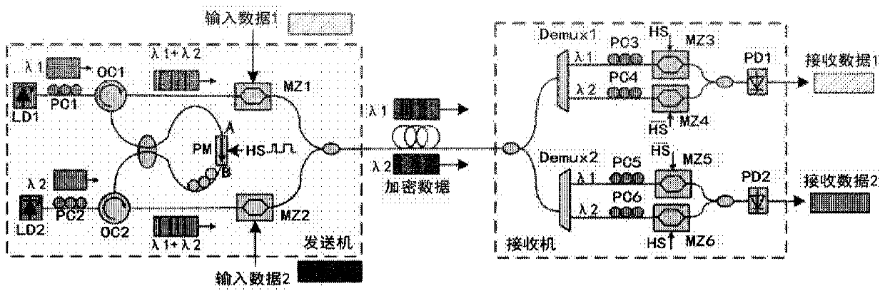
[0040] An embodiment of the present invention provides an optical frequency hopping system and transmitter based on an optical circulator, please refer to figure 1 , figure 1 It is a schematic structural diagram of an optical frequency hopping system based on an optical circulator in this embodiment. First, it needs to be explained that, figure 1 Shown in is only a two-way optical frequency hopping system, but this system is not limited to two but can be extended to any number. refer to figure 1 , the optical frequency hopping system provided by the present invention includes:

[0041] A ring modulation unit, the ring modulation unit includes a plurality of optical circulators, optical couplers, phase modulators and ps...


PUM


Abstract

The invention discloses an optical frequency hopping system based on an optical circulator and a transmitter. The optical frequency hopping system includes: an annular modulation unit, whereinthe annular modulation unit comprises a plurality of optical circulators; the first port of each optical circulator receives different optical carriers; a second port of each optical circulator is connected with an optical coupler, each optical coupler is connected with a phase modulator and is combined with frequency hopping coding in a pseudo-random code generator to realize coding modulation of an optical carrier signal, and a third port of each optical circulator respectively outputs the coded and modulated optical carrier signal; a transmitter which is internally provided with the annular modulation unit and is used for transmitting the optical carrier signal encrypted by the annular modulation unit; a receiver which is used for receiving the encrypted optical carrier signal and decrypting the encrypted optical carrier signal through frequency hopping coding; and an optical fiber which is used for realizing carrier communication between the transmitter and the receiver. According to the invention, high-speed optical frequency hopping coding can be realized, a flexible and simple unit structure is provided, expansion to a multi-channel optical frequency hopping system is facilitated, and a communication system with higher confidentiality is provided.

Description

technical field [0001] The invention relates to the field of optical communication security, in particular to an optical frequency hopping system based on an optical circulator. Background technique [0002] In today's information age, too much commercial confidential information and personal privacy information are transmitted through optical fiber networks every day. In the past, people always thought that optical fiber communication was very safe, but with the development of technology, optical fiber eavesdropping can be realized through optical fiber bending, beam splitting, evanescent wave coupling, scattering and other methods. Therefore, safe optical communication becomes a very important subject. [0003] At present, the improvement of communication security is mainly divided into software layer and hardware layer. The software layer includes algorithm encryption for user data, such as AES encryption, but all algorithm-based encryption methods have been proven to be...

Claims


Application Information

Patent Timeline
Patent Type & Authority Applications(China)
IPC IPC(8): H04B10/275H04B10/50H04B10/548H04L9/06H04L29/06
CPCH04B10/275H04B10/503H04B10/506H04B10/548H04L9/0662H04L63/0428
Inventor 齐艺超陈伟黄庆超祝宁华
Owner INST OF SEMICONDUCTORS - CHINESE ACAD OF SCI
Why Eureka
Try Eureka