Eureka AIR delivers breakthrough ideas for toughest innovation challenges, trusted by R&D personnel around the world.

Straw baler applicable to thresher

A baler and thresher technology, applied in the field of straw balers, can solve the problems of poor work coordination, cumbersome work, easy damage of keys, etc., and achieve the effect of flexible use and simple operation

Pending Publication Date: 2019-07-09
哈尔滨市金马农机配件制造有限公司
View PDF1 Cites 0 Cited by
  • Summary
  • Abstract
  • Description
  • Claims
  • Application Information

AI Technical Summary

Problems solved by technology

The grass level control mechanism is also an important part of the baler. The grass level control board in the grass level control mechanism also plays a corresponding role in the straw baling. In the existing grass level control mechanism, some of them are connected Defects such as complex structure, poor work coordination, and low work efficiency
The double forks used in the baler are connected to the crankshaft assembly through a key. After repeated use, the key is easily damaged and needs to be disassembled and replaced. The service life of the baler is long; the two support rods on the frame of the baler used to support the support of the rope needle are set under the frame, and it is difficult to ensure that the two support rods are on the same level. The reason is that it is easy to deform, which makes the position of the guide needle support deviate, causing the position of the guide rope to deviate, and the bundling cannot be completed; and the current balers are all used in harvesters, and cannot directly work on threshers.

Method used


Image

  • Straw baler applicable to thresher
  • Straw baler applicable to thresher
  • Straw baler applicable to thresher

Examples


Embodiment 1

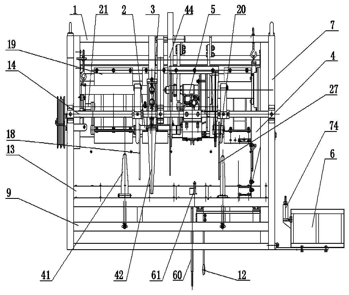
[0043] Such as figure 1 , figure 2 , image 3 , Figure 4 , Figure 5 , Figure 6 , Figure 7 , Figure 8 , Figure 9 , Figure 10 , Figure 11 , Figure 12 , Figure 13 , Figure 14 , Figure 15 , Figure 16 , Figure 17 , Figure 18 , Figure 19 , Figure 20As shown, a straw baler suitable for a thresher includes a frame 1, a grass feeding mechanism 2, a grass outlet mechanism 3, a grass level control mechanism 4, a bundling mechanism 5, a rope storage mechanism 6 and a power input mechanism , the grass feeding mechanism 2 is arranged at the rear end of the vehicle frame 1, the grass discharging mechanism 3 is arranged at the front end of the vehicle frame 1, and the baling mechanism 5 is arranged between the grass feeding mechanism 2 and the grass discharging mechanism 3 Between, the grass level control mechanism 4 is set on the right end of the frame 1, located on the right side of the bundling mechanism 5, and the storage rope mechanism 6 is set on the ...

Embodiment 2

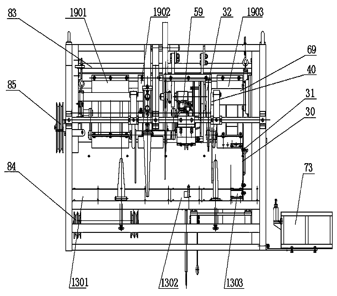
[0048] Such as figure 1 , figure 2 As shown, there is a certain distance between the head grass pressing plate 1901, the middle grass pressing plate 1902 and the root grass pressing plate 1903, leaving space for the grass feeding double fork 22 and the grass feeding single fork 27 activities. The double fork 22 and the grass-feeding single fork 27 are arranged at a certain angle, which is convenient for bringing the straw into the bundling position.

Embodiment 3

[0050] Such as figure 1 , figure 2 The power input mechanism includes a power shaft 83, an input drive pulley 84 and an input pulley 85. The power shaft 8383 is arranged inside the vehicle frame 1 through a bearing, and gears are arranged at both ends of the power shaft 83 to be connected with the vehicle. The gears on the side of the frame 1 are meshed with each other. The left side of the frame 1 is provided with an input pulley 85, and the bottom of the rear end of the frame 1 is provided with an input drive pulley 84. The center of the input pulley 85 is connected with the bearing through the bearing. The crankshaft 25 of the double-fork assembly 18 of grass feeding is connected. The crankshaft 25 is provided with a gear that meshes with the gear on the power shaft 83 . The left end of the input driving pulley 84 is connected with the input pulley 85 through a belt, and the right end of the input driving pulley 84 is connected with the threshing machine through a belt. ...


PUM


Abstract

The invention discloses a straw baler applicable to a thresher. The baler cooperates with the thresher to operate simultaneously and is installed on the rear portion of the rice thresher, operation iseasy, the working state of all mechanisms is table, a grass inlet double fork is connected with a crankshaft assembly through welding, damage is not likely to occur, and the total service life of thegrass inlet double fork is prolonged; two support rods on a frame of the baler are arranged on the upper portion of the frame and located on the same horizontal plane, deformation is not likely to occur, the position of a messenger needle support can be stable, the messenger position is stable and does not deviate, the baling efficiency is improved, a grass position control panel can flexibly adjusting grass root positions by connecting different mounting holes, and then the knot tying position is adjusted; installation and disassembling are conducted conveniently, a rope storing and feedingmechanism is detachably connected with the frame, the space is saved in the transportation process, and transportation is facilitated. The baler has the advantages of being simple in structure, flexible in transmission, good in work coordination, high in working stability, few in fault and high in adaptability to the working environment.

Description

technical field [0001] The invention relates to the technical field of crop straw bundling equipment, in particular to a straw bundling machine suitable for threshers. Background technique [0002] my country is a large agricultural country, and the straw resources produced by a large number of crops are very rich. Since straw is a good clean and renewable resource with good economic, ecological and social benefits, how to use straw as a clean and renewable resource has attracted more and more attention, such as biomass power generation. However, due to the problems of low density and inconvenient transportation and storage of crop straws, storing and transporting straws after bundling is the key to reducing the cost of raw material collection and storage and promoting the industrial utilization of straws. Therefore, the domestic market demand for baling machinery is also increasing. At the same time, the requirements for its performance are getting higher and higher. In ...

Claims


Application Information

Patent Timeline
IPC IPC(8): A01F15/00A01F15/10A01F15/12A01F15/08
CPCA01F15/00A01F15/08A01F15/10A01F15/12
Inventor 宁士才李金成
Owner 哈尔滨市金马农机配件制造有限公司
Why Eureka
Eureka Blog
Learn More