Charge combustion chamber shell and forming method thereof

A molding method and combustion chamber technology, which can be applied to jet propulsion devices, rocket engine devices, machines/engines, etc., can solve problems such as mismatching assembly surfaces of demoulding, deformed winding mandrels, high requirements for equipment conditions, and complicated process , to achieve the effect of simple and reliable manufacturing process, uniform spraying thickness and simple process

Active Publication Date: 2019-07-09
THE GENERAL DESIGNING INST OF HUBEI SPACE TECH ACAD
View PDF6 Cites 10 Cited by
  • Summary
  • Abstract
  • Description
  • Claims
  • Application Information

AI Technical Summary

Problems solved by technology

During production, the thermal insulation film is hand-paved in the molding die to the designed thickness, and a large press is used for pressure vulcanization (7-9) MPa. This process can improve the integrity of the thermal insulation layer, but the process is complicated and requires high equipment conditions. High, it is easy to cause the problem that the demoulding deformation does not match the assembly surface of the winding mandrel;
[0006] (3) Forming of the thermal insulation structure of the column section: according to the design thickness, the thermal insulation film is layered, segmented, and block-paved on the outer surface of the winding mandrel. The operation process is brushing, drying, bonding, and rolling ( The air wrapped in the adhesive interface is driven out of the interface to realize the seamless bonding between the thermal insulation materials), all of which are manually operated. The manual laying process of the thermal insulation film is mature and has a wide range of applications, but the process is backward, the labor intensity is high, and the molding quality is low. Strong dependence on the operator, unstable quality, prone to various quality defects such as debonding, dents, bulging, and delamination;

Method used

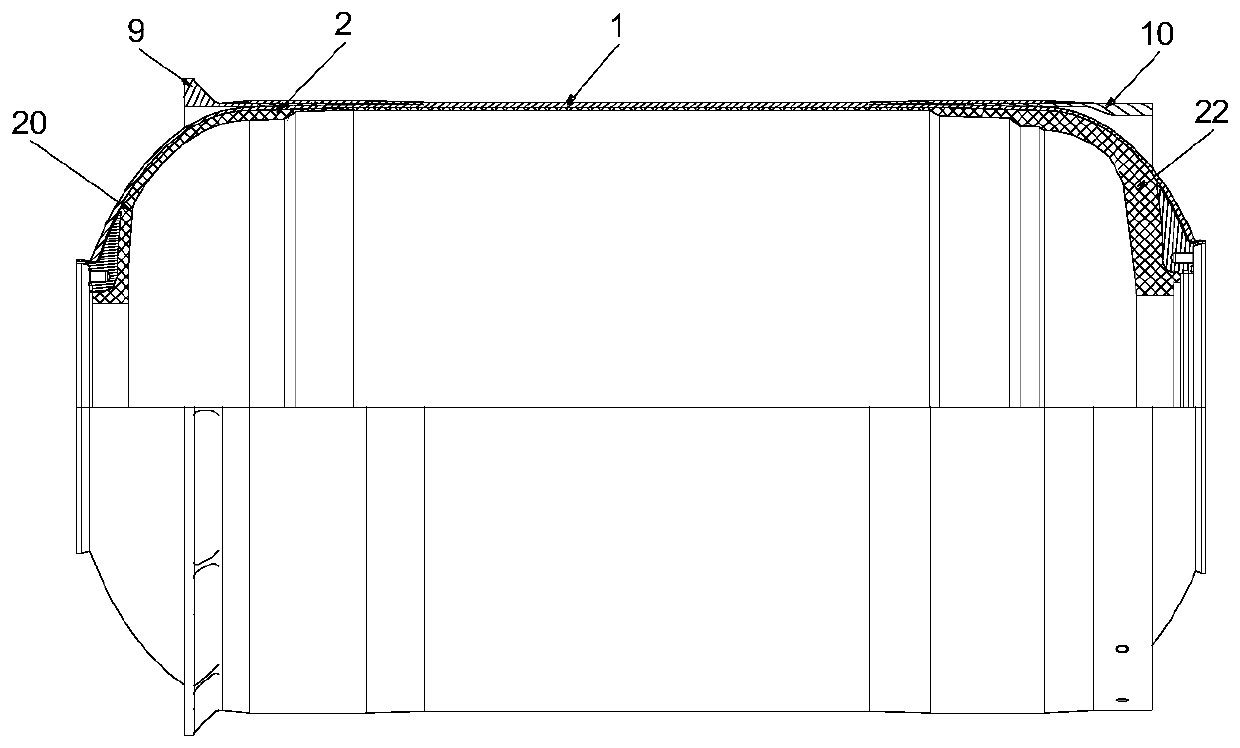

Image

  • Charge combustion chamber shell and forming method thereof
  • Charge combustion chamber shell and forming method thereof
  • Charge combustion chamber shell and forming method thereof

Examples


Embodiment Construction

[0051] The present invention will be described in further detail below in conjunction with the accompanying drawings and embodiments.

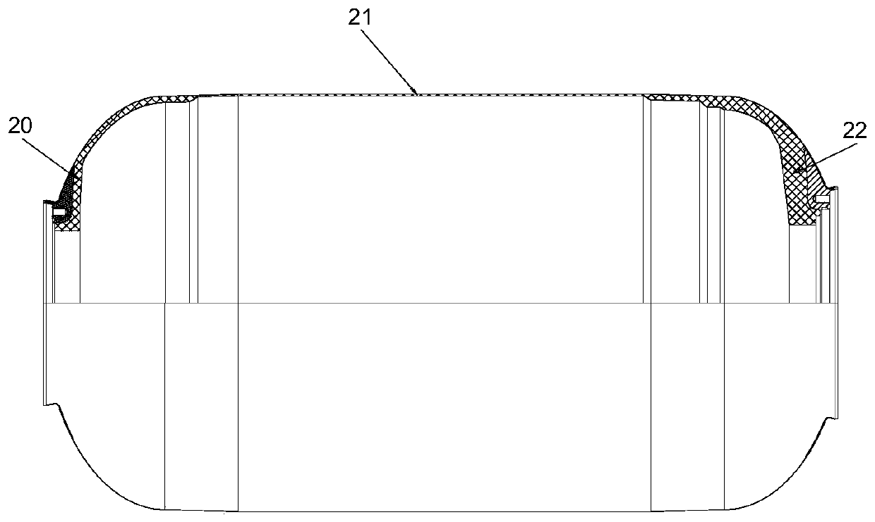
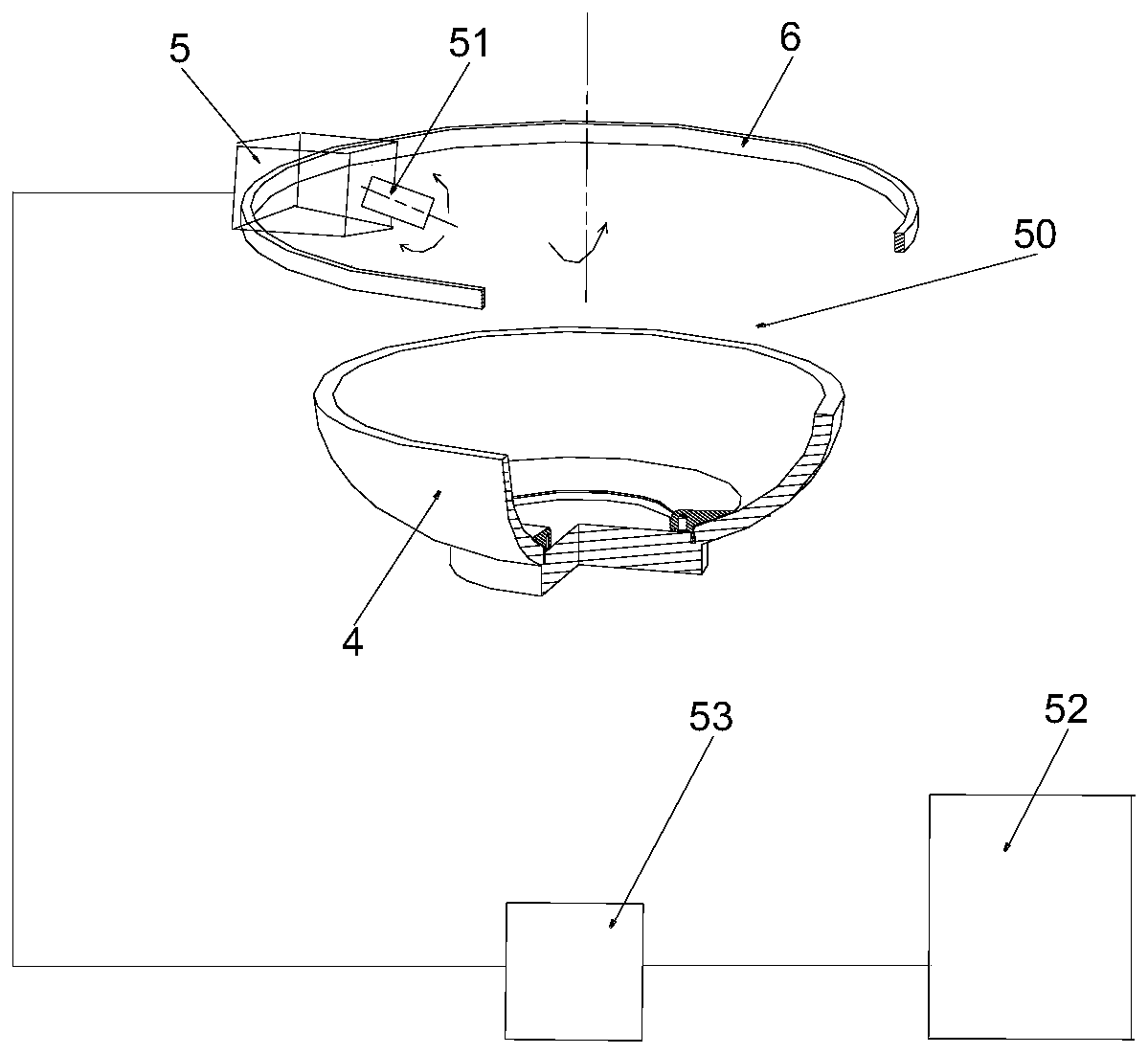
[0052] An embodiment of the present invention provides a method for forming a charge combustion chamber shell, see figure 1 and figure 2 As shown, the shell of the charge combustion chamber includes an outer shell 1 and a heat insulating layer 2, the heat insulating layer 2 is arranged on the inner surface of the outer shell 1, and the heat insulating layer 2 includes a front head heat insulating structure that is sequentially distributed and connected along the length direction of the outer shell 1 20. The thermal insulation structure 21 of the column section and the thermal insulation structure 22 of the rear head, wherein the thermal insulation structure 20 of the front header and the thermal insulation structure 22 of the rear header are formed separately, assembled on the winding mandrel 3, and then the thermal insulation structure 21 of...


PUM


Abstract

The invention discloses a forming method of a charge combustion chamber shell. The charge combustion chamber shell comprises an outer shell and a heat insulation layer, the heat insulation layer is arranged on the inner surface of the outer shell, and the heat insulation layer comprises a front seal head heat insulation structure, a column section heat insulation structure and a rear seal head heat insulation structure which are sequentially distributed and connected in the length direction of the outer shell. The forming method of the charge combustion chamber shell characteristically involves the following steps of providing a winding core model, a seal head mold and heat insulation slurry; spraying the heat insulation slurry in the seal head mold, and preparing the front seal head heatinsulation structure and the rear seal head heat insulation structure by adopting a press moulding manner; assembling the front seal head heat insulation structure and the rear seal head heat insulation structure on the winding core model; spraying the heat insulation slurry on the outer surface of the winding core model to form the column section heat insulation structure; winding fibers on the outer surface of the heat insulation layer to form the outer shell; and curing to form the charge combustion chamber shell.

Description

technical field [0001] The invention relates to the technical field of solid rocket motor manufacturing, in particular to a charge combustion chamber shell and a forming method thereof. Background technique [0002] With the increase in size and working time of solid rocket motors, in order to adapt to the harsh internal environmental conditions of the engine, the molding quality of the charge combustion chamber shell must be improved. [0003] The charge combustion chamber shell of the existing solid rocket motor includes an outer shell and an adiabatic structure. The adiabatic structure is composed of a front head adiabatic structure, a column section adiabatic structure and a rear end head adiabatic structure. The molding process of the charge combustion chamber casing is as follows : [0004] (1) Make the thermal insulation material into a thermal insulation film; [0005] (2) Forming of the heat insulation structure of the front head and the rear head: According to th...

Claims


Application Information

Patent Timeline
Patent Type & Authority Applications(China)
IPC IPC(8): F02K9/34
CPCF02K9/34
Inventor 司学龙武丹周睿陈文杰刘冬青郑振兴舒孟炯王川
Owner THE GENERAL DESIGNING INST OF HUBEI SPACE TECH ACAD
Why Eureka
Try Eureka