
Process for pneumatically conveying a powdery material

A powdery, pneumatic technology, applied in the direction of conveying bulk materials, chemical instruments and methods, conveyors, etc., can solve problems such as restoring normal pressure drop, amplification, etc., to improve efficiency and safety, and avoid inappropriate working frequency. Effect

Active Publication Date: 2019-07-09
LHOIST RECH & DEV SA
View PDF12 Cites 0 Cited by
  • Summary
  • Abstract
  • Description
  • Claims
  • Application Information

AI Technical Summary

Problems solved by technology

Of course, this fluctuation phenomenon is further amplified when conveying powdered materials (particularly powdered adsorbents), since as soon as powdered materials (especially powdered adsorbents) start to accumulate in the pneumatic conveying line, Cannot easily restore normal pressure drop on its own

Method used


Image

  • Process for pneumatically conveying a powdery material
  • Process for pneumatically conveying a powdery material
  • Process for pneumatically conveying a powdery material

Examples


Embodiment

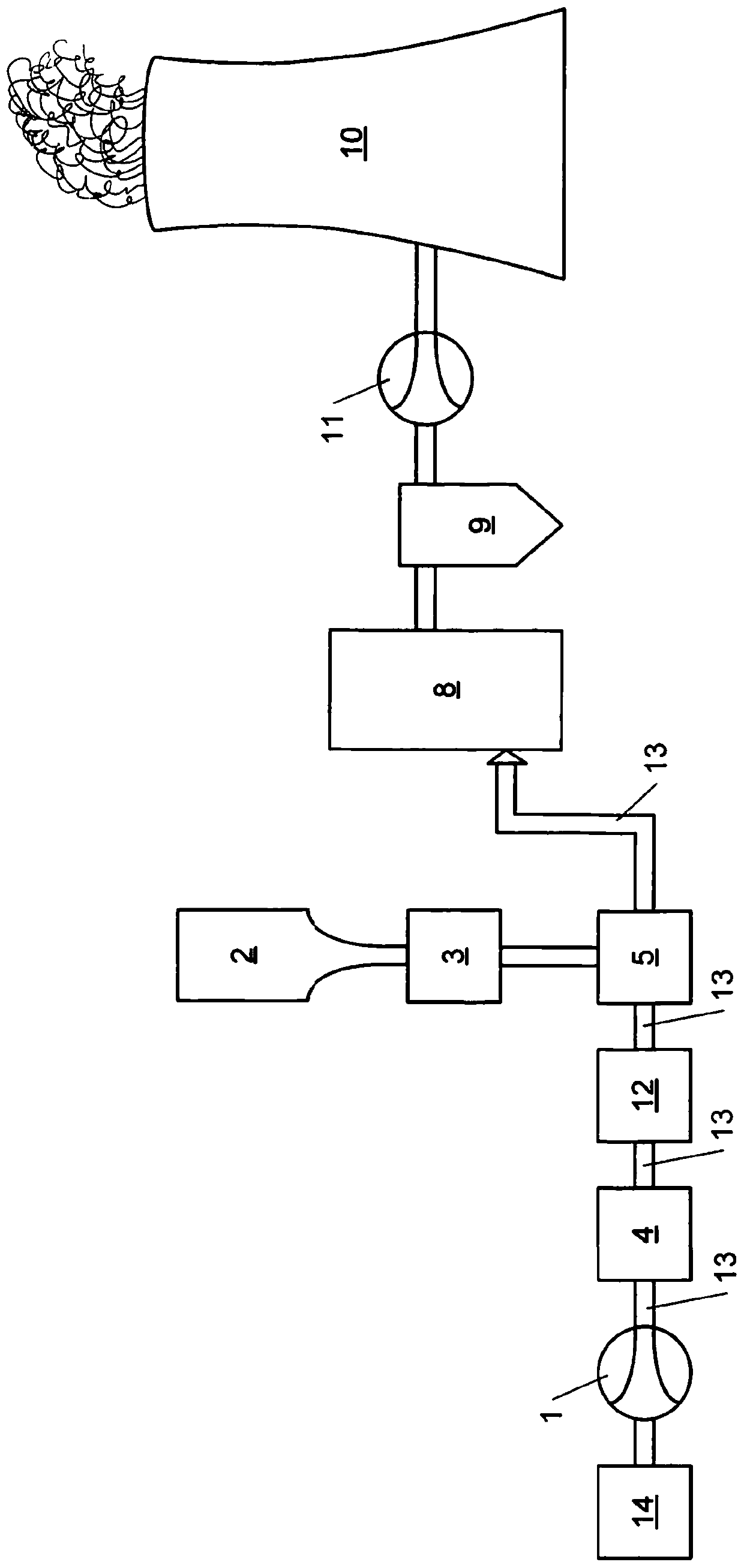
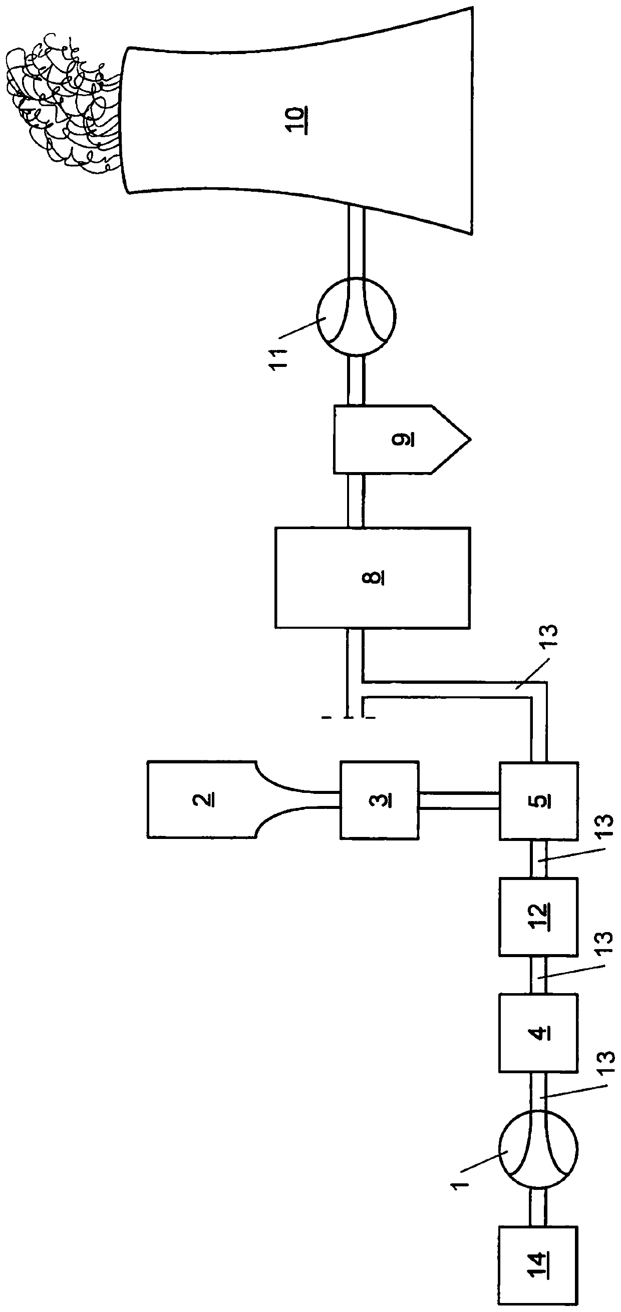
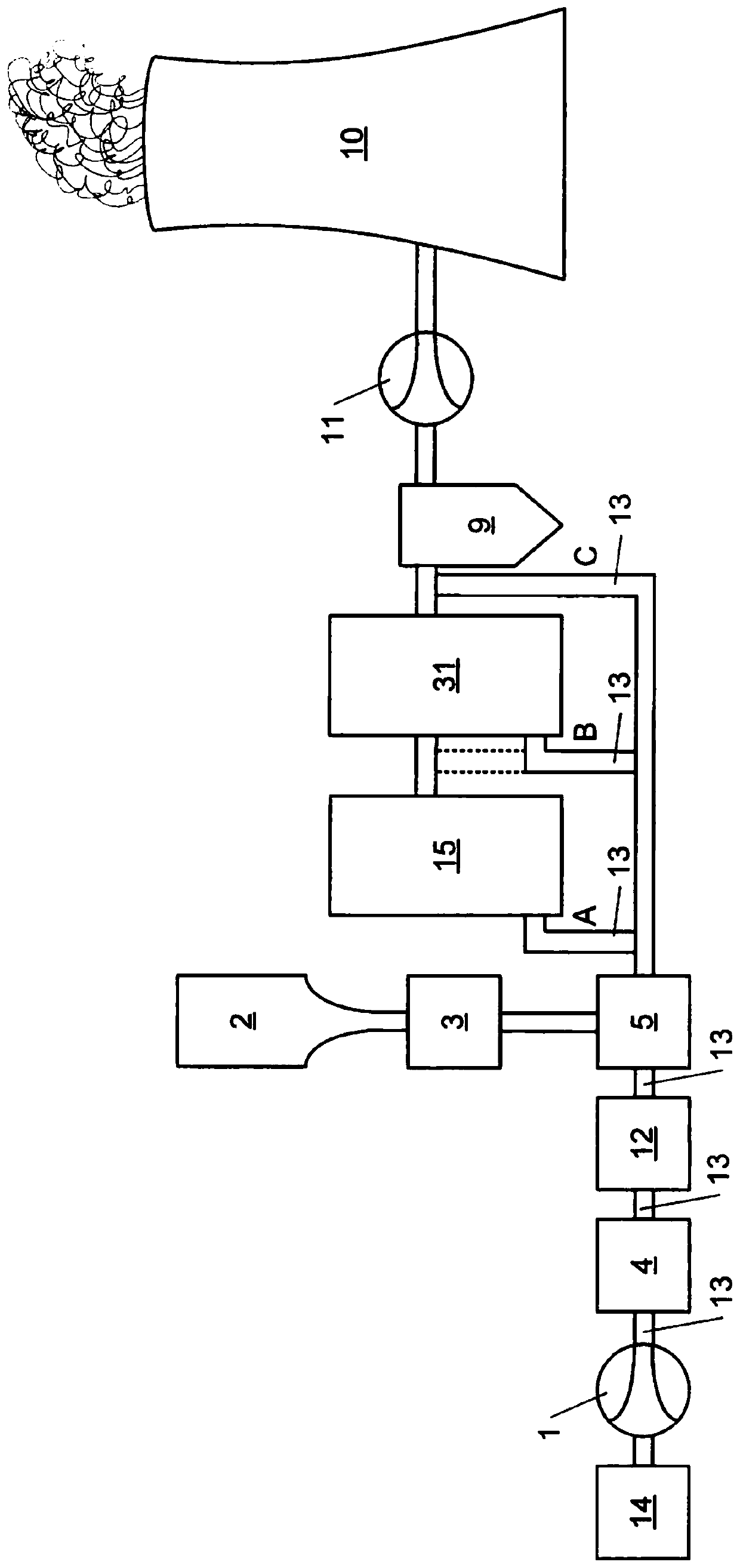
[0276] Trials were carried out on an industrial scale in a power plant to evaluate the effectiveness of the invention in pneumatically conveying a powdered hydrated lime adsorbent, especially with regard to fluctuations in the pressure drop within the plant.

[0277] Such as Figure 7 As shown, the electrical equipment used in these tests consisted of a burner (15), a furnace (31) for burning coal connected to a flue gas duct, wherein the flue gas produced in the furnace is directed to the electrostatic precipitator (9), then to the scrubber (32) and further to the chimney (10).

[0278] Hydrated lime is injected into the flue gas duct of the power plant before the electrostatic precipitator and before the chimney for capturing gaseous pollutants, especially SO 2 . Such an adsorbent is a high surface area hydrated lime as disclosed in WO9714650.

[0279] The plant also comprises a storage tank (2) for said powdered hydrated lime, said tank being connected to the furnace by ...


PUM


Abstract

The invention relates to a process and device for pneumatically conveying a powdery material. The process comprises the steps of: pneumatically conveying a powdery material in a pneumatic conveying pipeline (first) and into said recipient by a flow generated by a blower, a powdery material dosing step, a fluctuation step of pressure drop in said pneumatic conveying pipeline or up to said recipient, wherein a sonic device generates sonic waves inside said pneumatic conveying pipeline or up to said recipient and provides a counteraction on the fluctuation step of the pressure drop in said pneumatic conveying pipeline or up to said recipient.

Description

technical field [0001] The invention relates to a method for the pneumatic conveying of powdered materials, in particular powdered adsorbents, comprising the following steps: [0002] Pneumatically conveying powdered material, in particular powdered sorbent, in a first pneumatic transfer line from a powdered material storage tank, in particular a powdered sorbent storage tank, to a receiving area, wherein the first pneumatic transfer line comprises pipeline wall and is connected to the powdery material storage tank (in particular, the powdery adsorbent storage tank) and the receiving area, and the powdery material (in particular, the powdery adsorbent) is produced by a blowing machine The flow of is pneumatically conveyed in the first pneumatic conveying line and pneumatically conveyed to the receiver area, the blower is connected to the first pneumatic conveying line and blows the conveying fluid inside the first pneumatic conveying line, in In said transport fluid, said pow...

Claims


Application Information

Patent Timeline
Patent Type & Authority Applications(China)
IPC IPC(8): B01J8/00B65G53/00B65G53/06B65G53/34B65G53/66
CPCB01J8/0015B65G53/06B65G53/34B65G53/66B65G49/08
Inventor 胡格斯·巴奎特约翰·海斯沃尔夫乔伊尔·勒图西大卫·里昂斯查德·蒂莫西·梅茨霍华德·布拉克斯顿·菲茨杰拉德格雷戈里·M·菲利佩利
Owner LHOIST RECH & DEV SA
Learn More