
Flexible pure aluminum foil and glass fiber composite material machining mold

A technology of glass fiber and composite materials, which is applied in metal processing and other directions, can solve the problems of being unable to bear the extrusion force of the product, unable to detect defective products, and unable to achieve the effect, so as to eliminate defective products, excellent shielding performance, and meet product costs. The effect of pressure

Inactive Publication Date: 2019-07-12
苏州壬和控股有限公司
View PDF7 Cites 0 Cited by
  • Summary
  • Abstract
  • Description
  • Claims
  • Application Information

AI Technical Summary

Problems solved by technology

[0006] Deficiencies in the prior art: in the punching process, due to the extrusion around the edge of the die, the sponge is relatively soft and cannot withstand the extrusion force around the product, so the extrusion deformation around the product is relatively large, and the gradient often occurs. Tolerance phenomenon
Inspectors cannot detect defective products, resulting in inflow to clients
Therefore, the existing technology can only slightly alleviate the problem, and cannot achieve good results.

Method used


Image

  • Flexible pure aluminum foil and glass fiber composite material machining mold
  • Flexible pure aluminum foil and glass fiber composite material machining mold
  • Flexible pure aluminum foil and glass fiber composite material machining mold

Examples


Embodiment Construction

[0032] The specific implementation of this embodiment will be described below in conjunction with the accompanying drawings.

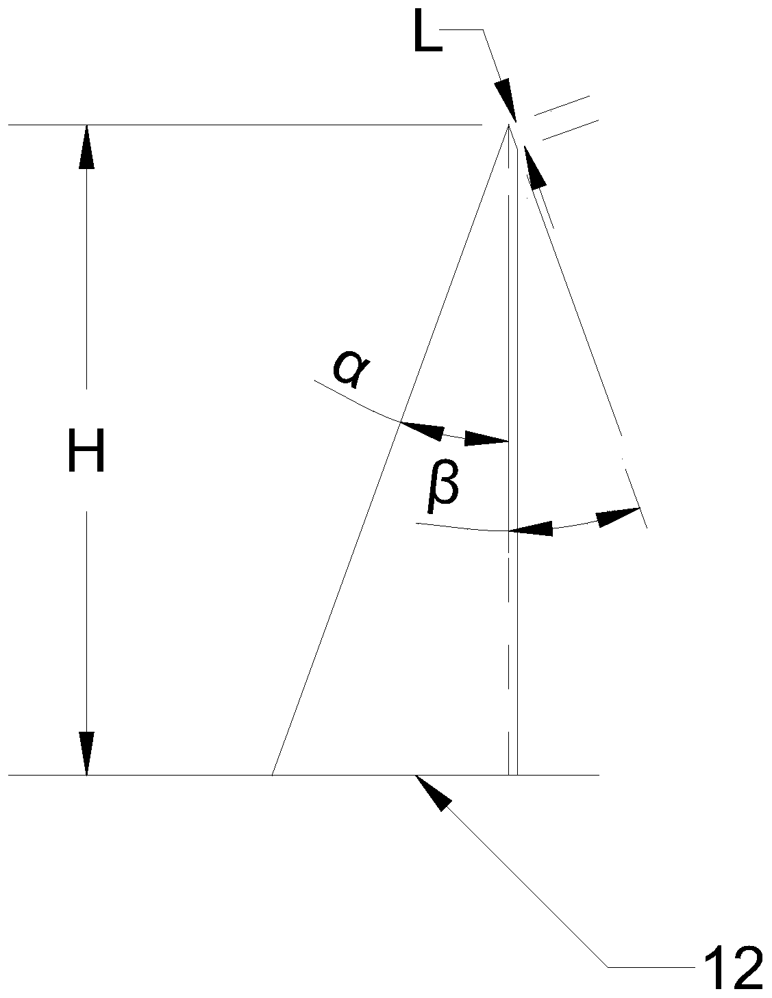
[0033] image 3 A schematic diagram of the blade. Such as image 3 As shown, the bending height H of the blade 12 is 1.5T, the purpose is to reduce the contact surface between the blade 12 and the incision, so as to reduce friction. The inner included angle α and the outer included angle β of the blade 12 are both 20°, and the length L of the edge of the blade 12 is 0.06 mm to prevent chipping.

[0034] Figure 4 It is a schematic diagram of the present invention. Such as Figure 4 As shown, a processing mold for flexible pure aluminum foil and glass fiber composite material includes an corrosion mold 1 , a first aluminum block 2 and a second aluminum block 3 . The corrosion mold 1 and the first aluminum block 2 are fixed by positioning PIN4.

[0035] Figure 5 for Figure 4 Schematic illustration of the corrosion mold in Fig. Such as Figur...


PUM

PropertyMeasurementUnit
heightaaaaaaaaaa
heightaaaaaaaaaa
lengthaaaaaaaaaa

Abstract

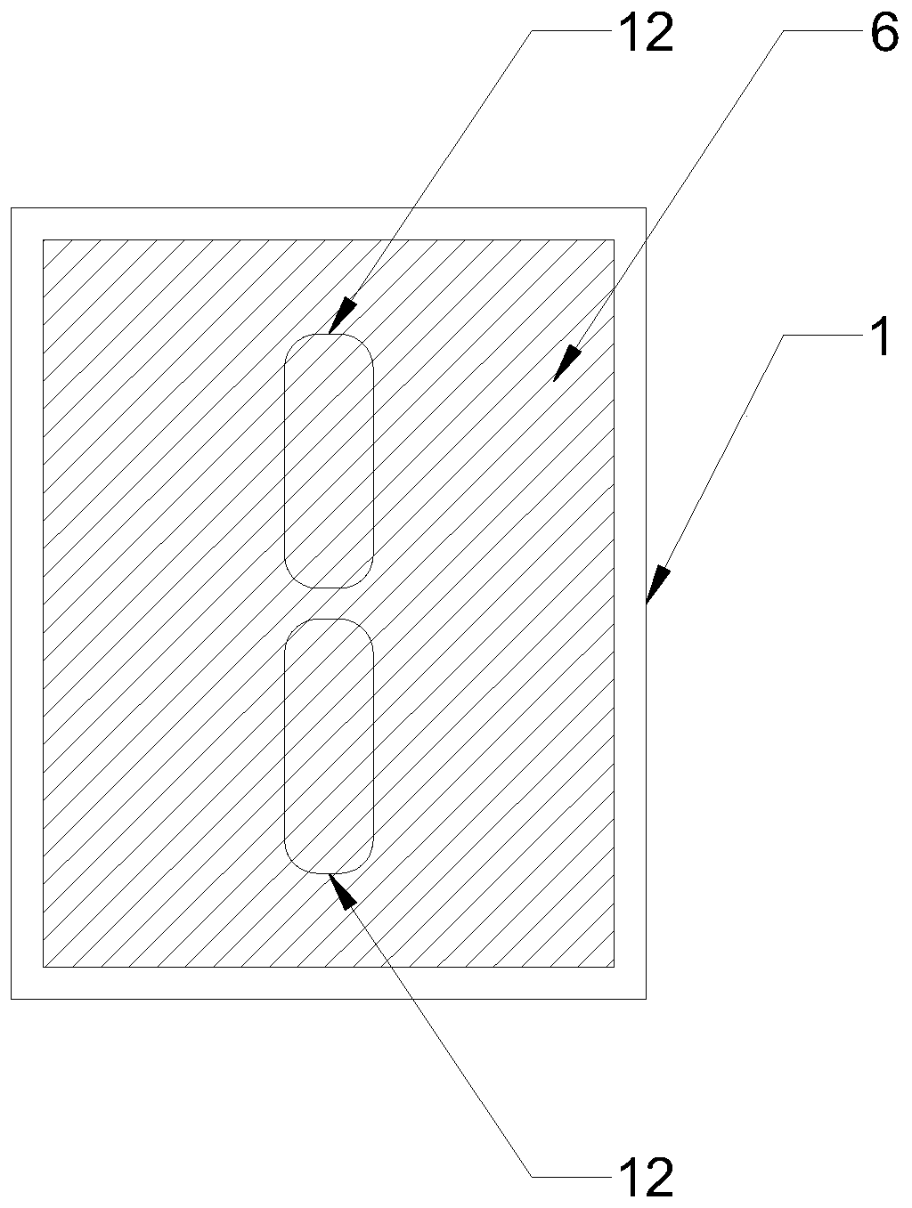
The invention relates to a flexible pure aluminum foil and glass fiber composite material machining mold. The mold comprises an etching mask, a first aluminum block and a second aluminum block. The etching mask and the first aluminum block are fixed through locating PINs; two kidney-shaped holes which are distributed side by side are formed in the etching mask; blades are embedded into the peripheries of the kidney-shaped holes; a first groove which is used for embedding the locating PINs and positioning pins is formed in the first aluminum block; a supporting seat is disposed at the bottom ofthe first groove; a second groove which is used for embedding the locating PINs and the positioning pins is formed in the second aluminum block; the outer walls of the locating PINs are sleeved withsprings; and the locating PINs and the positioning pins are inserted into the first groove and the second groove in sequence, and the second aluminum block is embedded into the first groove so as to be fixedly connected. By means of the flexible pure aluminum foil and glass fiber composite material machining mold, the effect that the slope of the periphery of a punched opening of a product is uniform is guaranteed, and the slope of the periphery is smaller than or equal to 0.1 mm.

Description

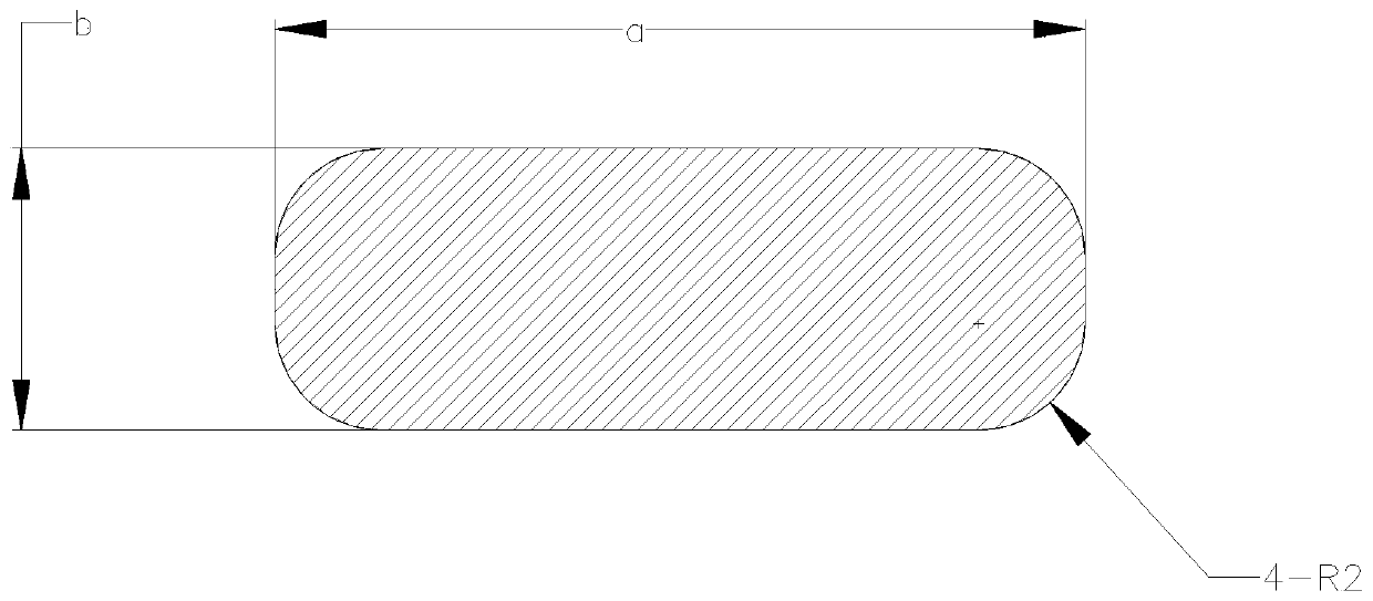
technical field [0001] The invention relates to the field of die-cutting processing, in particular to a processing die for soft pure aluminum foil and glass fiber composite materials. Background technique [0002] figure 1 A schematic diagram of the composite material. Such as figure 1 As shown, in the voice control module, composite materials are often used, that is, the two surfaces of a layer of foam are respectively bonded with soft pure aluminum foil coated with a metal conductive layer, which is used to reduce the conductive resistance of the contact surface and resist corrosion. Connector assembly metallization compatibility. [0003] The design length a of the product is 16.0790mm±0.025mm, the design width b of the product is 5.5900mm±0.025mm, the edge of the product is chamfered, and the edge of the product is marked with a 4-R2 processing line. The cutting surface of the product is required to be ≤0.01mm. Customers have extremely strict requirements on the fla...

Claims


Application Information

Patent Timeline
Patent Type & Authority Applications(China)
IPC IPC(8): B26F1/40B26F1/44B26D7/26
CPCB26D7/2614B26F1/40B26F1/44B26F2001/4472
Inventor 周军
Owner 苏州壬和控股有限公司
Learn More