[0031] The following will clearly and completely describe the technical solutions in the embodiments of the present invention with reference to the accompanying drawings in the embodiments of the present invention. Obviously, the described embodiments are only part of the embodiments of the present invention, not all of them. Based on the embodiments of the present invention, all other embodiments obtained by persons of ordinary skill in the art without creative efforts fall within the protection scope of the present invention.
[0032] It should be noted that if there is a directional indication (such as up, down, left, right, front, back, top, bottom, etc.) in the embodiment of the present invention, the directional indication is only used to explain the position in a certain posture ( As shown in the accompanying drawings), if the specific posture changes, the directional indication will also change accordingly.
[0033] In addition, if there are descriptions involving "first", "second" and so on in the embodiments of the present invention, the descriptions of "first", "second" and so on are only for descriptive purposes, and should not be interpreted as indicating or implying Its relative importance or implicitly indicates the number of technical features indicated. Thus, the features defined as "first" and "second" may explicitly or implicitly include at least one of these features. In addition, the technical solutions of the various embodiments can be combined with each other, but it must be based on the realization of those skilled in the art. When the combination of technical solutions is contradictory or cannot be realized, it should be considered that the combination of technical solutions does not exist , nor within the scope of protection required by the present invention.
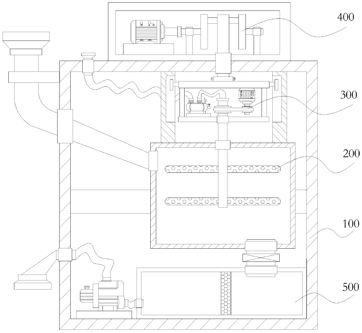
[0034] like Figure 1 to Figure 2 As shown, the present invention proposes a papermaking waste liquid treatment device, including a frame 100, an aeration mechanism 200 arranged on the frame 100, a rotating mechanism 300 connected to the aeration mechanism 200, and a rotating mechanism connected to the rotating mechanism 300. The lifting mechanism 400 and the filtering mechanism 500 connected with the aeration mechanism 200 . The frame 100 can provide an installation foundation and a supporting foundation for the whole device, and the aeration mechanism 200 can be used for aerating the papermaking waste liquid. Moreover, the rotating mechanism 300 can rotate the aeration mechanism 200, and the lifting mechanism 400 can lift up and down the rotating mechanism 300 and the aeration mechanism 200, so that the aeration position of the aeration mechanism 200 can be changed, the aeration area can be increased, and the aeration mechanism can be improved. Aeration efficiency.
[0035]Moreover, the above-mentioned rack 100 may include a main box body having an accommodating cavity, and an installation base disposed in the middle of the accommodating cavity. The above-mentioned aeration mechanism 200 can be installed on the mounting seat, the above-mentioned filter mechanism 500 can be arranged at the bottom of the main box and located in the containing cavity, and the filter mechanism 500 is located under the aeration mechanism 200 . In this way, it is convenient to use the aeration mechanism 200 to aerate the papermaking waste liquid, and then use gravity to flow into the filter mechanism 500 for filtration. Moreover, the above-mentioned rotating mechanism 300 can be arranged on the top of the aeration mechanism 200 and located in the accommodation chamber, and the above-mentioned lifting mechanism 400 can be arranged on the top of the main box and located outside the accommodation chamber. By arranging the rotating mechanism 300 in the main box, it is convenient to be connected with the aeration mechanism 200 to rotate it. And by setting the lifting mechanism 400 outside the main box body, it is convenient to connect and rotate the rotating mechanism 300, and the volume of the main box body can also be reduced. In addition, the aeration mechanism 200, the rotation mechanism 300, and the filter mechanism 500 can be accommodated and sealed by setting the main box body with the accommodating cavity, so that the whole device forms an integral structure.
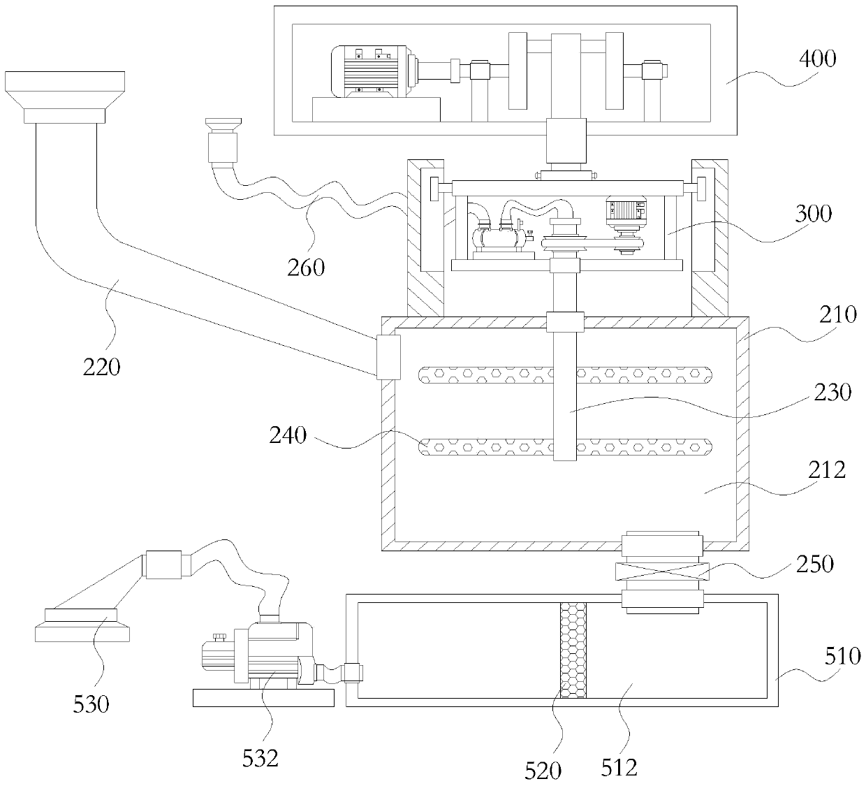
[0036] In addition, if Figure 3 to Figure 4 As shown, the above-mentioned aeration mechanism 200 may include an aeration box 210 with an aeration chamber 212, a liquid inlet pipe 220 connected to the upper part of the aeration box 210 and communicated with the aeration chamber 212, connected to the lower part of the aeration box 210 and the The liquid outlet pipe 250 between the filter mechanisms 500 and communicated with the aeration chamber 212, the aeration pipe structure located in the aeration chamber 212 and protruding from the top of the aeration box 210, and the aeration pipe structure communicating with the aeration pipe structure Breathing structure. Through the liquid inlet pipe 220 located on the upper part of the aeration box 210 (including the upper side and the top of the aeration box 210), the papermaking waste liquid to be treated can be input into the aeration chamber 212 of the aeration box 210, and the suction structure can be used to Air can be delivered to the aeration light structure, and then the air can be aerated to the papermaking waste liquid in the aeration chamber 212 by using the aeration tube structure installed in the aeration chamber 212, and then passed through the aeration tube structure installed at the bottom of the aeration box 210 The liquid outlet pipe 250 discharges the aerated papermaking waste liquid and transports it to the filter mechanism 500 for filtering and storage. In addition, the above-mentioned liquid inlet pipe 220 can protrude from the accommodating cavity of the main box to the upper part of the main box (including the upper side and the top of the main box, and is located above the aeration box 210), so as to facilitate the passage of papermaking waste liquid. The liquid inlet pipe 220 is delivered to the aeration box 210 .
[0037] Further, the above-mentioned aeration pipe structure may include an air inlet pipe 230 protruding from the top of the aeration box 210 into the aeration chamber 212 , and an aeration pipe body arranged on the air inlet pipe 230 and located in the aeration chamber 212 240, the aeration pipe body 240 communicates with the air intake pipe 230, and the aeration pipe body 240 is provided with a plurality of aeration holes. Moreover, the air suction structure may include an air suction pipe 260 communicating with the air intake pipe 230 , and an air suction pump 262 disposed on the air suction pipe 260 . The air is sucked into the suction pipe 260 by the air suction pump 262, and the air is delivered to the air intake pipe 230 of the aeration pipe structure through the air suction pipe 260, and then delivered to the aeration pipe body 240 communicated with the air intake pipe 230 , and through a plurality of aeration holes provided on the aeration pipe body 240, the air is transported into the papermaking waste liquid in the aeration chamber, and the papermaking waste liquid is aerated. In addition, the suction pipe 230 protrudes from the accommodating chamber of the main box to the outside of the main box, and can be arranged on the top of the main box to facilitate air suction. In addition, in this embodiment, a plurality of aeration pipe bodies 240 may be connected to the suction pipe 260 , and the inner cavity of each aeration pipe body 240 communicates with the inner cavity of the suction pipe 260 . Moreover, the suction pipe 260 can be vertically arranged in the aeration chamber 212, and each aeration pipe body 240 can be vertically arranged on the suction pipe 260, and the two ends of each aeration pipe body 240 can be arranged with respect to The suction pipes 260 are arranged symmetrically.
[0038] In addition, the above-mentioned rotating mechanism 300 can be arranged on the top of the aeration box 210 and connected with the air inlet pipe 230 of the aeration pipe structure for rotating the aeration pipe structure. That is, the air intake pipe 230 and the aeration pipe body 240 connected to the air intake pipe 230 can be rotated by the rotating mechanism 300, so that the position of the aeration pipe body 240 in the aeration chamber in the aeration box 210 can be changed, which can increase the Large aeration area. Moreover, the above-mentioned lifting mechanism 400 can be arranged on the frame 100 and connected with the rotating mechanism 300 for driving the rotating mechanism 300 and the aeration tube structure to move up and down. The air intake pipe 230 and the aeration pipe body 240 of the aeration pipe structure are driven by the lifting mechanism 400 to move up and down in the aeration chamber of the aeration box 210, so that the height of the aeration pipe structure in the aeration chamber can be changed, and the height of the aeration pipe structure can also be increased. Large aeration area. In this way, by setting the rotating mechanism 300 and the lifting mechanism 400, not only the air intake pipe 230 and the aeration pipe body 240 can be rotated, but also can be lifted up and down, which can better increase the aeration area of the aeration pipe structure.
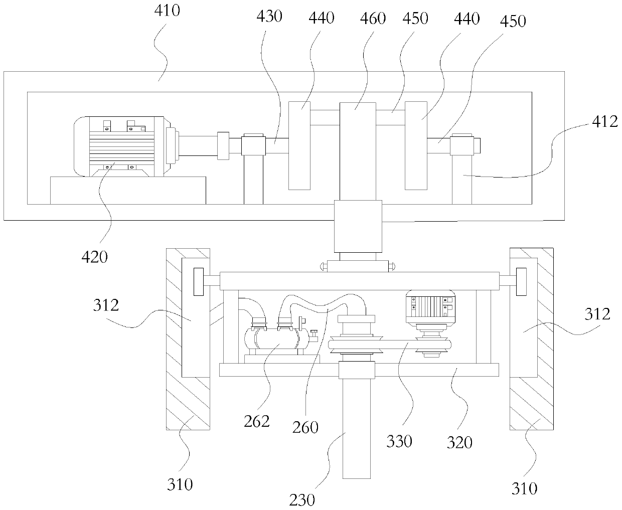
[0039] Further, the rotation mechanism 300 may include support frames 310 arranged on both sides of the top of the aeration box 210, a support platform 320 provided between the support frames 310 on both sides, and a rotary driving structure 330 provided on the support platform 320 , the rotation driving structure 330 is connected with the end of the air intake pipe 230 protruding from the aeration box 210 . The rotating driving structure 330 can be supported by the support frame 310 and the supporting platform 320 , and the intake pipe 230 can be rotated by the rotating driving structure 330 . Moreover, the rotating mechanism 300 is located in the accommodating chamber and at the top of the aeration box 210 , and can be conveniently connected with the air intake pipe 230 to prevent the air intake pipe 230 from protruding too much out of the aeration box 210 . In addition, the supporting frames 310 on both sides can be connected between the top of the aeration box 210 and the inner top wall of the main box, and the rotating mechanism 300 is separated in the accommodating chamber of the main box to prevent papermaking waste liquid from intruding into the rotating mechanism 300 .
[0040] Moreover, the support table 320 may include a first horizontal plate 322 and a second horizontal plate 324 arranged side by side, and a connecting plate 326 connected between the first horizontal plate and the second horizontal plate, the first horizontal plate 322 or/and Both ends of the second horizontal plate 324 are respectively connected to the support frame 310 . The support platform 320 formed by two horizontal bars arranged side by side and the connecting rod connected between the two horizontal bars can provide stable and reliable support and fixation for the rotation driving structure 330 . Moreover, the above-mentioned rotary driving structure 330 includes a first driving motor 332 arranged on the first horizontal plate 322 or the second horizontal plate 324, connected to the driving pulley 334 on the output shaft of the first driving motor 332, connected to the intake pipe The driven pulley 336 at the end of 230, and the driving belt 338 connected between the driving pulley 334 and the driven pulley 336. That is to say, the rotary drive structure 330 is set as a belt drive structure, the driving pulley 334 can be driven to rotate by the first driving motor 332, and the driven pulley 336 is driven to rotate by the transmission belt 338, so as to drive the belt connected to the driven pulley 336. The intake pipe 230 rotates. Moreover, in order to facilitate the rotation of the intake pipe 230 , the suction pipe 260 can be connected to the top of the intake pipe 230 through a rotating connector, so that the suction pipe 260 can normally deliver air to the intake pipe 230 .
[0041] Moreover, the above-mentioned second horizontal plate 324 can be located directly above the top of the aeration box 210, the first horizontal plate 322 is located directly above the second horizontal plate 324, and the two connecting plates 326 are respectively connected to the first horizontal plate 322 and the second horizontal plate 324 , and the first drive motor 332 is hoisted below the first horizontal plate 322 , and the end of the intake pipe 230 is rotatably mounted on the second horizontal plate 324 . By hoisting the first drive motor 332 and the driving pulley 334 below the first horizontal plate 322, and setting the intake pipe 230 and the driven pulley 336 on the second horizontal plate 324, the driving pulley can be better aligned like this. Matching with the driven pulley can also reduce the force of a single horizontal plate. In addition, the above-mentioned suction pump 262 can also be arranged on the second horizontal plate 324, which is relatively close to the end of the intake pipe 230, so as to be conveniently connected with the intake pipe 230 through a pipeline.
[0042] In addition, the lifting mechanism 400 may include a second drive motor 420 disposed on the frame 100 , and a slider crank structure connected to the second drive motor 420 , and the slider crank structure is connected to the support platform 320 of the rotation mechanism 300 . By setting the slider crank structure, the slider crank structure can be driven by the second drive motor 420, so that the slider crank structure drives the support platform 320 to slide up and down, thereby driving the second horizontal plate 324 connected to the support platform 320. The air intake pipe 230 and the aeration pipe body 240 move up and down.
[0043] Specifically, the slider crank structure described above may include a rotating bracket 412 arranged on the frame 100, rotating a first rotating shaft 430 arranged on the rotating bracket 412 and connected to the second drive motor 420 at one end, and connected to the first rotating shaft 430. The rotating disc 440 at the other end of the rotating shaft 430, the second rotating shaft 450 disposed on the peripheral side of the rotating disc 440, and the push rod 460 that is sleeved on the second rotating shaft 450, the push rod 460 is hinged on the supporting platform 320, and the first rotating shaft 430 and the second rotating shaft 450 are respectively disposed on two sides of the turntable 440 , and the two are misaligned. Moreover, sliding grooves 312 are defined inside the supporting frames 310 on both sides, and both ends of the supporting platform 320 are slidably disposed in the sliding grooves 312 on both sides. That is, the second driving motor 420 can drive the first rotating shaft 430 disposed on the rotating bracket 412 to rotate, thereby driving the turntable 440 and the second rotating shaft 450 to rotate. Moreover, due to the misalignment of the first rotating shaft 430 and the second rotating shaft 450 , an eccentric rotation structure is formed, so that the rotation of the two is not synchronized, so that the second rotating shaft 450 can be rotatably socketed and hinged to the support table 320 The push rod 460 will push the support platform 320 to slide up and down along the direction of the sliding groove 312 of the support frame 310, that is, it can drive the air intake pipe 230 and the aeration pipe body 240 connected to the support platform 320 to move up and down. That is, the above-mentioned crank slider structure can be set as a crankshaft rocker drive structure, which is similar to the crankshaft structure of an automobile.
[0044] Moreover, in some embodiments, a rotating bracket 412 may be provided at both ends of the frame 100, each rotating bracket 412 is rotatably provided with a first rotating shaft 430, and each first rotating shaft 430 is connected with a turntable 440, and the second rotating shaft 450 is connected between the two turntables 440, the push rod 460 is rotatably set in the middle of the second rotating shaft 450, and the second drive motor 420 is connected to a first rotating shaft 430, and the two first rotating shafts 430 They are disposed on the same axis, and the second rotating shaft 450 is misaligned with the two first rotating shafts 430 . That is to say, the two first rotating shafts 430 and the two turntables 440 are arranged symmetrically with respect to the push rod 460 to balance the force on the structure, make the rotation of the second rotating shaft 450 more stable, and drive the push rod 460 more stably and reliably. In addition, the above-mentioned lifting mechanism 400 can also include a lifting box body 410 located at the top of the main box body of the frame, and the above-mentioned second driving motor 420 and the slider crank structure are arranged in the lifting box body 410, and these structures are Sealed for protection.
[0045] In addition, if figure 2 As shown, the filter mechanism 500 may include a filter box 510 disposed on the bottom of the housing chamber of the main box of the frame 100, a filter cavity 512 formed in the filter box 510, and a filter cavity 512 separated from the filter cavity 512. The filter screen 520, and the drain pipe 530 located at the bottom of the filter box body 510 and communicated with the filter chamber 512, the liquid outlet pipe 250 is connected to the top of the filter box body 510 and communicated with the filter chamber 512, and the liquid outlet pipe 250 and the drain pipe The tubes 530 are respectively located on both sides of the filter screen 520 . After aeration, the papermaking waste liquid flows from the aeration chamber 212 of the aeration box 210 into the filter chamber 512 of the filter box 510 through the liquid outlet pipe 250, and the filter screen 520 arranged in the filter chamber 512 can also be used to The papermaking waste liquid is filtered, and then can be discharged through the drain pipe 530 . Moreover, the filter box 510 can also be used as a liquid storage tank to store the aerated papermaking waste liquid. In addition, in order to facilitate the discharge of the liquid in the filter chamber 512 , a water pump 532 may also be provided on the drain pipe 530 to suck the liquid in the filter chamber 512 . In addition, the drain pipe 530 also protrudes out of the main box, and the outlet of the drain pipe 530 is set at the bottom of the main box.
[0046] In the technical solution proposed by the present invention, the aeration tube structure in the aeration chamber inside the aeration box can be rotated by setting a rotating mechanism, and at the same time, the aeration tube structure can be lifted and lowered by the lifting mechanism, which can be continuously Adjust the position of the aeration tube structure, that is, enhance the mobility of the aeration tube, flexibly control the height and angle of the aeration tube structure in the water, increase the area of aeration in the water, increase the oxygenation power, and enhance the efficiency of papermaking. The treatment effect of waste liquid.