Spot plating electrode module and spot plating device

A module and spot plating technology, applied in the direction of electrodes, electrolytic components, electrolytic processes, etc., can solve the problems of increasing processing procedures, material waste, and increasing production costs, and achieve the goals of reducing procedures, ensuring spray volume, and reducing plating solution waste Effect

Pending Publication Date: 2019-07-12
安徽永基电子科技有限公司
View PDF0 Cites 1 Cited by
  • Summary
  • Abstract
  • Description
  • Claims
  • Application Information

AI Technical Summary

Problems solved by technology

[0003] When electroplating electronic components, most of the electroplating equipment used in the prior art is a plating solution tank, and the workpiece is immersed in the plating solution tank for overall electroplating. This method will cause the parts of the parts to be plated that do not need to be electroplated to be electroplated A layer of metal, and the excess electroplating usually needs to be cut off, or the excess plating should be ground off, which not only causes a waste of materials, but also increases the processing procedures, resulting in an increase in production costs

Method used


Image

  • Spot plating electrode module and spot plating device
  • Spot plating electrode module and spot plating device
  • Spot plating electrode module and spot plating device

Examples


Embodiment Construction

[0037] The present invention will be described in detail below in conjunction with the drawings and embodiments.

[0038] This specific embodiment is only an explanation of the present invention, and it is not a limitation of the present invention. After reading this specification, those skilled in the art can make modifications to this embodiment without creative contribution as needed, but as long as the rights of the present invention All requirements are protected by patent law.

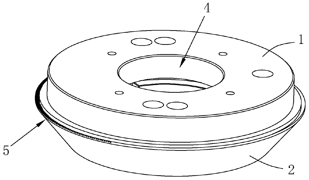
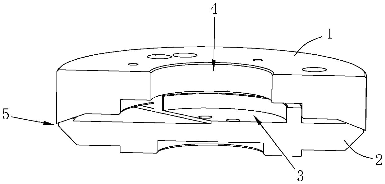
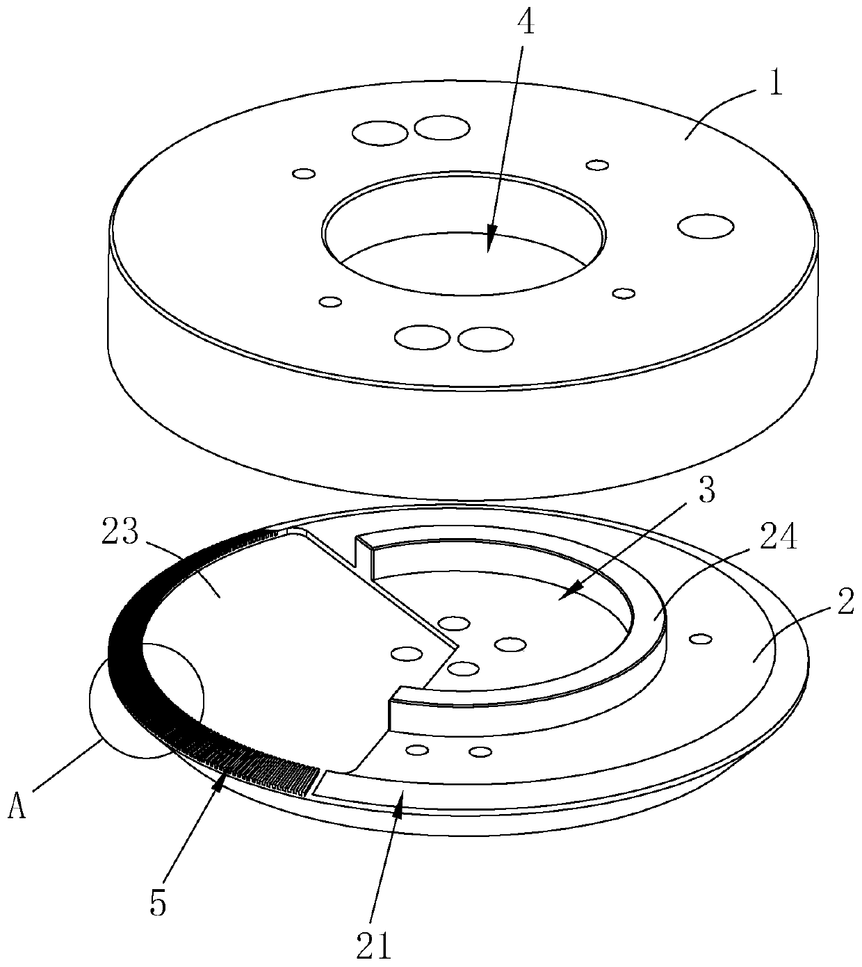
[0039] A spot plating device includes a spot plating motor module, refer to figure 1 , The spot-plating electrode module includes an insulating upper cover 1 and an insulating lower cover 2.

[0040] Reference figure 1 and figure 2 , The insulating upper cover 1 is in the shape of a round cover, and its edge extends downward to cover the insulating lower cover 2. The insulating upper cover 1 and the insulating lower cover 2 are attached to each other to form a cavity 3 in the center of the two. In ad...


PUM

PropertyMeasurementUnit
angleaaaaaaaaaa

Abstract

The invention discloses a spot plating electrode module and a spot plating device, and relates to the field of electroplating. The device comprises an insulating upper cover and an insulating lower cover, wherein the insulating upper cover and the insulating lower cover are encircled to form a cavity, a through hole for plating liquid pressed into the cavity is formed in the insulating upper cover, the butt joint surface of the insulating lower cover and the insulating upper cover is provided with a liquid outlet communicating with the cavity, the liquid outlet comprises a plurality of liquidspraying grooves extending outwards along the butt joint surface, and anode coating is coated on the inner walls of the liquid spraying grooves. The insulating upper cover and the insulating lower cover encircle to form a cavity, the plating liquid is pressed into the cavity through the through hole, liquid spraying grooves extending outwards is arranged on the butt joint surface of the insulatinglower cover, and the liquid spraying grooves communicate with the cavity; when the plating liquid is pressed into the cavity, the liquid is sprayed outwards through the liquid spraying grooves, and then the liquid is accurately sprayed onto the material belt through the liquid spraying grooves, the redundant plating liquid is not needed to be removed, so that the plating liquid is saved, the working procedures are reduced, and the electroplating efficiency is improved; the anode coating coated on the inner walls of the liquid spraying grooves can enhance the conductivity of the inner walls ofthe liquid spraying grooves and accelerate the electron flow speed, and the spot plating is high in adhesion degree, fast in speed and is more uniform.

Description

Technical field [0001] The invention relates to electroplating technology, more specifically, it relates to a spot plating electrode module and a spot plating device. Background technique [0002] Electroplating is the process of plating a thin layer of other metals or alloys on the surface of certain metals using the principle of electrolysis. It is a process of using electrolysis to attach a metal film to the surface of a metal or other material to prevent metal oxidation. Improve wear resistance, electrical conductivity, reflectivity, corrosion resistance and enhance aesthetics. [0003] When electroplating electronic components, most of the electroplating equipment used in the prior art is a plating bath. The workpiece is immersed in the bath for overall electroplating. This method will cause the parts to be plated that do not need to be electroplated. A layer of metal, and the excess electroplating part usually needs to be cut off, or the excess plating layer is ground off, w...

Claims


Application Information

Patent Timeline
Patent Type & Authority Applications(China)
IPC IPC(8): C25D5/02C25D5/08C25D17/12C25D17/00
CPCC25D5/026C25D17/00C25D17/12
Inventor 周和平
Owner 安徽永基电子科技有限公司
Why Eureka
Try Eureka