
A laser emitting and receiving device, a furnace coke loss monitoring system and method

A laser emission and detection method technology, applied in the direction of optical devices, measuring devices, instruments, etc., can solve problems such as increasing the workload of power plant operation and maintenance personnel, excess thermal power installed capacity, and affecting the safe and economical operation of units

Active Publication Date: 2021-05-25
ELECTRIC POWER RESEARCH INSTITUTE OF STATE GRID SHANDONG ELECTRIC POWER COMPANY +1
View PDF0 Cites 0 Cited by
  • Summary
  • Abstract
  • Description
  • Claims
  • Application Information

AI Technical Summary

Problems solved by technology

[0002] With the need for the sustainable development of my country's electric power industry and the national economy, clean energy such as wind power, solar energy, and nuclear power are connected on a large scale, and the installed capacity of thermal power is severely surplus. More and more power plants have to reduce power generation by burning economical coal. cost, leading to increasingly prominent boiler coking problems, seriously affecting the safe and economical operation of the unit, and increasing the workload of power plant operation and maintenance personnel
At the same time, with the development of information technology in recent years, the willingness to build a smart power plant has become stronger. The basis of a smart power plant is the improvement of the terminal monitoring system. Since the coking problem occurs in a high-temperature environment in the furnace, the monitoring of coking in the furnace is very important. Difficult. At present, the technicians only judge the coke loss inside the boiler through the flame detection signal and experience, and determine which wall the coke falls to. At present, there is no reliable technical means to accurately determine the coking position during the hot operation process.

Method used


Image

  • A laser emitting and receiving device, a furnace coke loss monitoring system and method
  • A laser emitting and receiving device, a furnace coke loss monitoring system and method
  • A laser emitting and receiving device, a furnace coke loss monitoring system and method

Examples


Embodiment 1

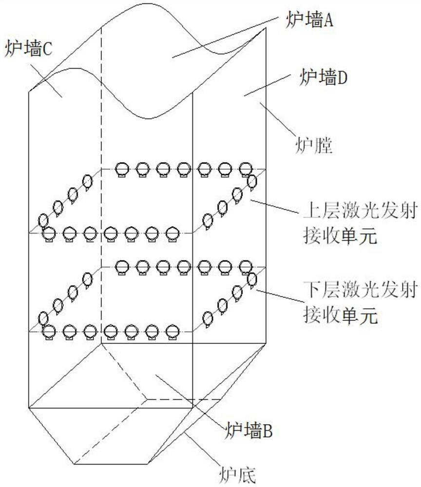
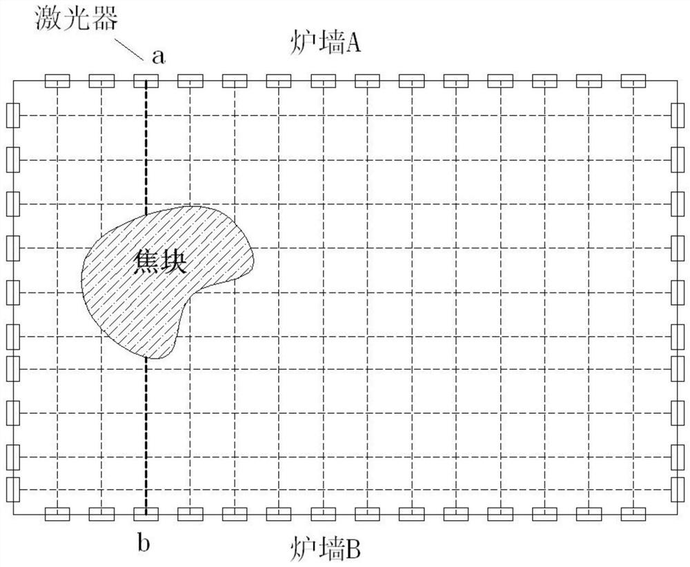
[0043] like figure 1 As shown, the laser emitting and receiving device is arranged at the bottom of the boiler, including two layers of upper laser emitting and receiving units and lower laser emitting and receiving units arranged in parallel and separated by a certain vertical distance. The upper and lower laser emitting and receiving units respectively include several Only uniformly arranged lasers, two lasers arranged on the opposite wall respectively measure the horizontal distance from the laser to the falling coke block in the boiler. The laser is arranged outside the bottom wall of the boiler, and the laser is incident through the hole arranged on the bottom wall of the boiler. The temperature at the bottom of the boiler is already low, but by setting the laser on the outside of the bottom wall of the boiler, the influence of lowering the temperature of the bottom of the boiler on the laser can be further isolated.

[0044] In this embodiment, the upper laser emitting ...

Embodiment 2

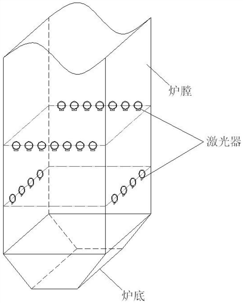
[0048] like image 3 As shown, the upper laser emitting and receiving unit includes lasers evenly arranged on furnace wall A and furnace wall B, and the lower layer laser emitting and receiving unit includes lasers evenly arranged on furnace wall C and furnace wall D; furnace wall A and furnace wall B are one A set of opposite furnace bottom walls; said furnace wall C and furnace wall D are another set of relative furnace bottom walls.

Embodiment 3

[0050] like Figure 4 As shown, the upper laser emitting and receiving unit includes lasers evenly arranged on furnace wall A and furnace wall D, and the lower laser emitting and receiving unit includes lasers evenly arranged on furnace wall B and furnace wall C; furnace wall A and furnace wall D are a A group of adjacent walls; the furnace wall B and furnace wall C are another group of adjacent walls.

[0051] like Figure 5 As shown, the coke loss monitoring system in the furnace includes a laser emitting and receiving device installed at the bottom of the boiler, a signal processing unit electrically connected to the laser emitting device, and a display terminal electrically connected to the signal processing unit.

[0052] The distance between the laser transmitter and receiver determines the accuracy of the observable focal block, the smaller the arrangement interval, the smaller the observable focal block. When the coke block falls from the upper part of the furnace an...


PUM


Abstract

The invention discloses a laser emitting and receiving device, which is arranged at the bottom of a boiler, and comprises two upper layer laser emitting and receiving units and a lower layer laser emitting and receiving unit arranged in parallel and separated by a certain vertical distance. The receiving units respectively include several uniformly arranged lasers, and the two lasers arranged on opposite walls respectively measure the horizontal distance from the lasers to the coke blocks dropped in the boiler. Also disclosed is a coke drop monitoring system and method in the furnace, which can obtain the height and horizontal position of the coke pieces falling in the furnace, so as to know the location of serious coking or large coke in the furnace, so as to carry out targeted operation adjustments measure. The overall coking and coke loss status in the furnace can be obtained, and the coal quality can be fed back according to the amount of coke, and the slagging equipment can be adjusted according to the monitoring results of the coke amount.

Description

technical field [0001] The invention relates to the technical field of thermal power generation, in particular to a laser emitting and receiving device, a coke drop monitoring system and method in a furnace. Background technique [0002] With the need for the sustainable development of my country's electric power industry and the national economy, clean energy such as wind power, solar energy, and nuclear power are connected on a large scale, and the installed capacity of thermal power is severely surplus. More and more power plants have to reduce power generation by burning economical coal. The cost has led to the increasingly prominent problem of boiler coking, seriously affecting the safe and economical operation of the unit, and increasing the workload of power plant operation and maintenance personnel. At the same time, with the development of information technology in recent years, the willingness to build a smart power plant has become stronger. The basis of a smart po...

Claims


Application Information

Patent Timeline
Patent Type & Authority Patents(China)
IPC IPC(8): G01B11/00
CPCG01B11/00
Inventor 刘科张徐东王海超刘景龙张利孟张绪辉王守恩侯凡军郭新根杨兴森胡志宏
Owner ELECTRIC POWER RESEARCH INSTITUTE OF STATE GRID SHANDONG ELECTRIC POWER COMPANY
Learn More