Ignition loss rate tester and testing method

A technology of thermal loss rate and testing method, which is applied in the testing of machines/structural components, instruments, measuring devices, etc., which can solve the problems of human interference, heavy workload, and error-prone test results, and reduce inhalation The risk of toxic and harmful gases, the possibility of reducing the possibility of errors, and the effect of reducing the time of contact with samples

Pending Publication Date: 2019-07-12
湖南三德盈泰环保科技有限公司
View PDF0 Cites 4 Cited by
  • Summary
  • Abstract
  • Description
  • Claims
  • Application Information

AI Technical Summary

Problems solved by technology

[0009] 1. The thermal loss on ignition test of the sample needs to go through the process of "weighing-drying-cooling-weighing-burning-cooling-weighing". If constant weight is required, "burning-cooling-weighing" is also required The whole test process requires manual operation, the workload is very heavy, the test efficiency is low, and the operation of weighing and counting is cumbersome and prone to errors;
[0010] 2. Since the test of thermal loss rate is carried out in a high-temperature environment, some samples will produce toxic and harmful gases when burned, so it will have a great impact on the health of the staff, and due to manual operation, the test results are susceptible to human interference, and there may be human interference. risk of fraud

Method used


Image

  • Ignition loss rate tester and testing method
  • Ignition loss rate tester and testing method

Examples


Embodiment Construction

[0045] The present invention will be further described in detail below in conjunction with the accompanying drawings and specific embodiments.

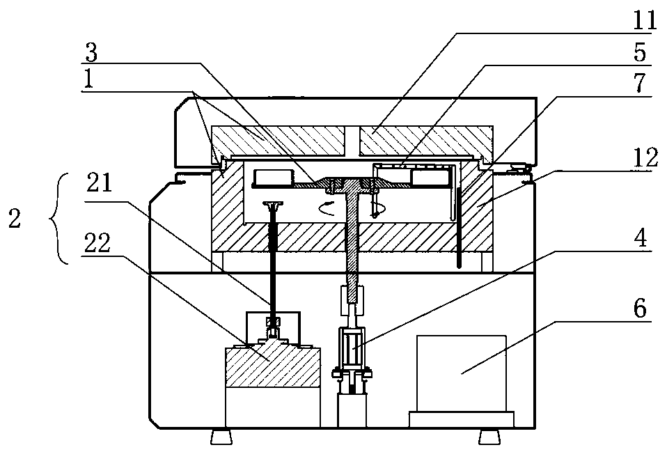
[0046] Such as figure 1 As shown, a thermal loss rate tester includes a housing, and the housing is provided with a heating and heat preservation device 1, a weighing mechanism 2, a lofting plate 3, a lifting and rotating mechanism 4, a ventilation device 5, a controller 6; a lofting plate 3 Set in the heating and heat preservation device 1, the lifting and rotating mechanism 4 is connected with the lofting disk 3, and is used to drive the lofting disk 3 to rotate and lift, and the weighing mechanism 2 is arranged under the lofting disk 3, and is used for weighing and ventilating the crucible The device 5 is arranged in the heating and heat preservation device 1, and is used to pump gas into the heating and heat preservation device 1. The controller 6 is connected with the lifting and rotating mechanism 4 and the weighing mechanism 2,...


PUM


Abstract

The invention discloses an ignition loss rate tester which comprises a shell, and a heating and heat preservation device, a weighing mechanism, a sample placing disc, a lifting and rotating mechanism,a ventilation device and a controller are arranged in the shell; wherein the sample placing disc is arranged in the heating and heat preservation device, the lifting and rotating mechanism is connected with the sample placing disc, the weighing mechanism is arranged below the sample placing disc, the ventilation device is arranged in the heating and heat preservation device, and the controller isconnected with the lifting and rotating mechanism and the weighing mechanism and used for controlling the lifting and rotating mechanism to move and storing and processing weighing data. The invention also discloses a test method based on the thermal ignition loss rate tester, which comprises the following steps: S1, weighing the weight of the empty crucible, putting a sample, drying the sample and weighing; S2, setting the temperature and the constant temperature time required by sample ignition, and cooling to room temperature after ignition is completed; and S3, weighing the mass of the fired crucible, and calculating the ignition loss rate through mass loss. According to the invention, full-automatic testing of the ignition loss rate is realized.

Description

technical field [0001] The invention relates to the technical field of thermal loss-on-ignition analysis of combustible substances, in particular to a thermal loss-on-ignition tester and a testing method. Background technique [0002] The thermal loss rate refers to the percentage of the mass of the incineration residue reduced by burning to the original incineration residue mass. For example, the thermal loss rate of waste incineration slag is the most powerful basis for judging whether the incinerator is normal or not, and it can reflect that the waste incineration machinery is not burned. Loss, calculate the completion status of waste incineration, regularly measure the rate of loss of heat on ignition, and check the abnormality and aging degree of the incinerator. In the incineration treatment of domestic waste, the control of the thermal ignition loss rate of incineration slag is very important, and plays a vital role in realizing the resource utilization, volume reduct...

Claims


Application Information

Patent Timeline
Patent Type & Authority Applications(China)
IPC IPC(8): G01N5/04G01M99/00
CPCG01M99/005G01M99/008G01N5/04
Inventor 胡亚军吴成乞文盼李冬军
Owner 湖南三德盈泰环保科技有限公司
Why Eureka
Try Eureka