Laser sodium guide satellite full emission link compensation system

A laser sodium guide star and compensation system technology, applied in the field of laser sodium guide star full launch link compensation system, can solve the problems of sodium guide star angle width increase, laser distortion, reduction correction and high-resolution imaging effect, etc. , to achieve the effect of good distribution characteristics

Inactive Publication Date: 2019-07-12
CHANGCHUN INST OF OPTICS FINE MECHANICS & PHYSICS CHINESE ACAD OF SCI
View PDF0 Cites 3 Cited by
  • Summary
  • Abstract
  • Description
  • Claims
  • Application Information

AI Technical Summary

Problems solved by technology

First, when the laser power density is high, the thermal distortion of the optical element and the distortion of the optical path inside and outside the laser cavity caused by mechanical deformation will lead to distortion of the wave front when the laser oscillates and transmits in the optical system. Leads to poor beam transmission quality factor
The second is that the laser will be disturbed by atmospheric turbulence during the upward transmission process, the

Method used


Image

  • Laser sodium guide satellite full emission link compensation system
  • Laser sodium guide satellite full emission link compensation system
  • Laser sodium guide satellite full emission link compensation system

Examples


Embodiment Construction

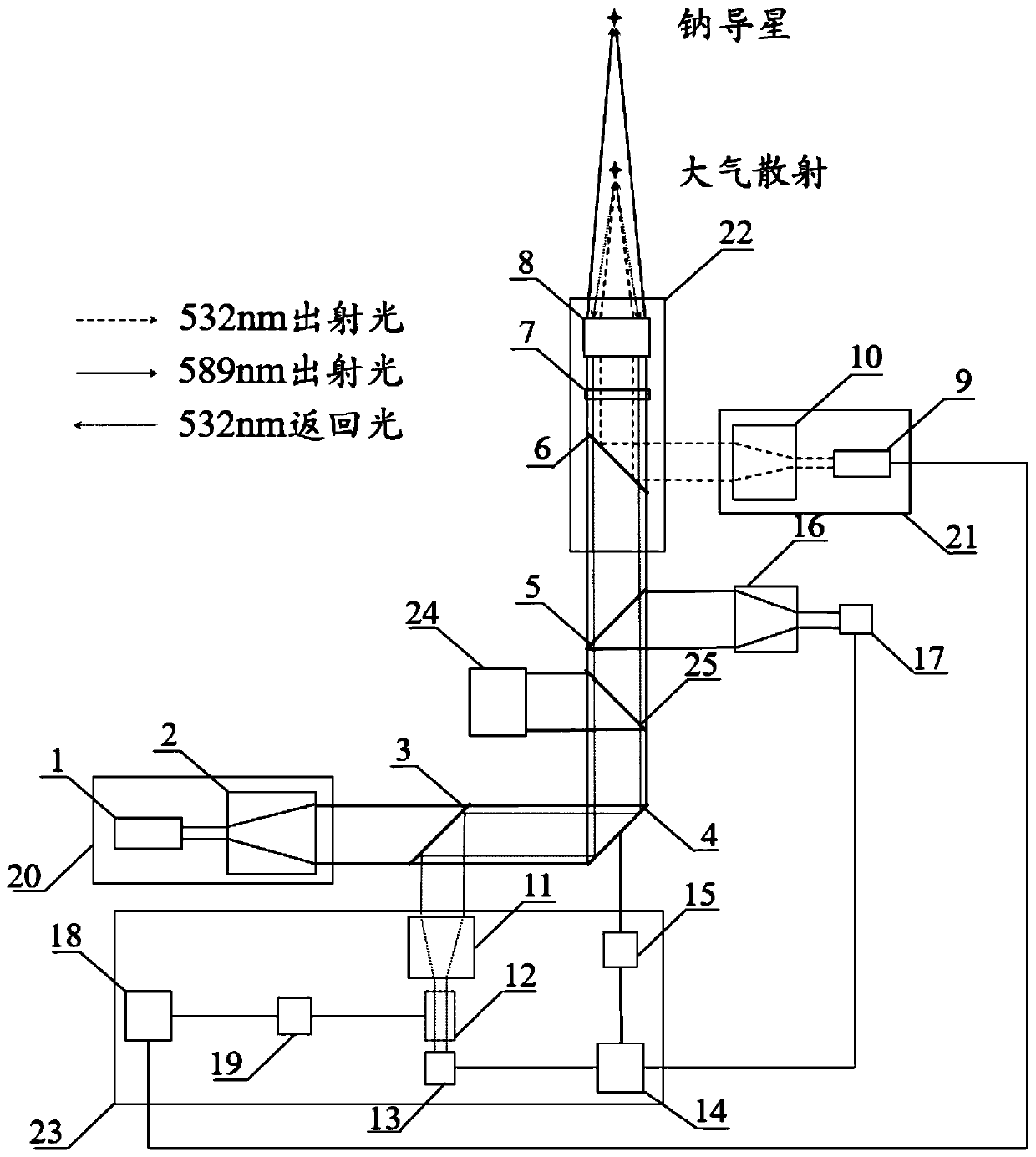
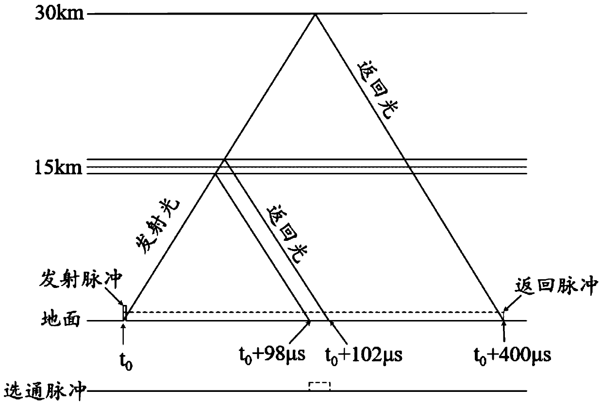
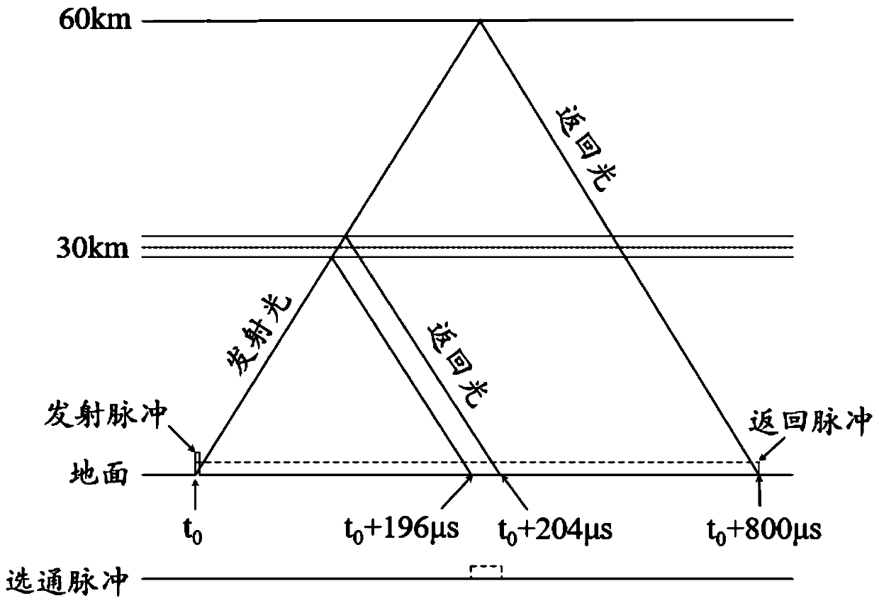
[0024] In order to make the object, technical solution and advantages of the present invention clearer, the present invention will be further described in detail below in conjunction with the accompanying drawings and specific embodiments. It should be understood that the specific embodiments described here are only used to explain the present invention, not to limit the present invention.

[0025] In order to make the description of the present disclosure more detailed and complete, the following provides an illustrative description of the implementation modes and specific examples of the present invention; but this is not the only form for implementing or using the specific embodiments of the present invention. The description covers features of various embodiments as well as method steps and their sequences for constructing and operating those embodiments. However, other embodiments can also be used to achieve the same or equivalent functions and step sequences.

[0026] T...


PUM


Abstract

The invention relates to the technical field of adaptive optical systems, in particular to a laser sodium guide satellite full emission link compensation system. The laser sodium guide satellite fullemission link compensation system comprises a first laser beam expanding system, a color selective mirror, a deformation mirror, a spectroscope, and a beam combining and beam expanding system which are arranged successively along an emission path, a second laser beam expanding system, a first beam shrinking device, a first wave front detector, a wave front detection and control system, and a reflecting mirror, and a calibration light source, wherein the first laser beam expanding system, the color selective mirror, the deformation mirror, the spectroscope, and the beam combining and beam expanding system are arranged in sequence along an emission path, the second laser beam expanding system is located in the incident direction of the beam combining and beam expanding system, the first beamshrinking device and the first wave front detector arranged successively are located on the reflection direction of the spectroscope, the wave front detection and control system is located on the reflection direction of the spectroscope, and the reflecting mirror and the calibration light source are arranged between the deformation mirror and the spectroscope. According to the laser sodium guidesatellite full emission link compensation system, distortions of sodium laser, abeam expanding transmission light path, and atmosphere turbulences are compensated by using a single deformable mirror,a double wave front detector and another laser with a different wavelength from the sodium laser to ensure that the sodium laser has good distribution characteristics and sodium guide satellite lightspot qualities when the sodium laser reaches a sodium layer.

Description

technical field [0001] The invention relates to the technical field of adaptive optical systems, in particular to a laser sodium guide star full-launch link compensation system. Background technique [0002] Sodium laser guide star technology refers to the use of a beam of laser whose central frequency can resonate with the transition line of sodium atoms to excite the sodium layer at a height of about 92km from the ground to emit resonant backscattered light, which is used as the guiding light source of the adaptive optics system and has sampling Highly advanced advantages. However, in practical applications, the wavefront of the sodium guide star laser beam will be degraded by interference from two aspects. First, when the laser power density is high, the thermal distortion of the optical element and the distortion of the optical path inside and outside the laser cavity caused by mechanical deformation will lead to distortion of the wave front when the laser oscillates an...

Claims


Application Information

Patent Timeline
IPC IPC(8): G02B26/08G02B27/10G02B27/28
CPCG02B26/0825G02B27/1006G02B27/283
Inventor 刘杰王建立陈涛刘欣悦林旭东李洪文李宏壮
Owner CHANGCHUN INST OF OPTICS FINE MECHANICS & PHYSICS CHINESE ACAD OF SCI
Why Eureka
Try Eureka