Multiple thermal fluid generation system with injection function and method of system

A systematic and multi-component technology, applied in the direction of mixing methods, chemical instruments and methods, and mining fluids, can solve problems such as seal failure, cumbersome operation, and inability to ensure the effectiveness of stirring, and achieve the goal of ensuring reliability and sealing reliability Effect

Inactive Publication Date: 2019-07-16
CHONGQING UNIVERSITY OF SCIENCE AND TECHNOLOGY
View PDF1 Cites 1 Cited by
  • Summary
  • Abstract
  • Description
  • Claims
  • Application Information

AI Technical Summary

Problems solved by technology

[0004] At present, mechanical stirring and magnetic stirring are widely used in various laboratories and manufacturing sites, but due to the limitations of sealing elements and magnet materials, they can basically only meet high-pressure fluid stirring at around 200 ° C, and due to the rubber material of the O-ring, The dynamic seal is often lower than 200 degrees Celsius, and the static seal can reach 250 degrees Celsius in a short time, which leads to the temperature limit of the existing container, and the fluid injection and proportioning operation is more troublesome; there are also stirring containers with a temperature of more than 200 degrees Celsius on the market, but Its sealing structure is complicated, the operation is cumbersome, and the cost is high
The sealing elements of mechanical stirring generally use rubber or polytetrafluoroethylene sealing rings, which are prone to aging, d

Method used


Image

  • Multiple thermal fluid generation system with injection function and method of system
  • Multiple thermal fluid generation system with injection function and method of system
  • Multiple thermal fluid generation system with injection function and method of system

Examples


Embodiment Construction

[0039] In order to make the object, technical solution and advantages of the present invention more clear, the present invention will be further described in detail below in conjunction with the examples. It should be understood that the specific embodiments described here are only used to explain the present invention, not to limit the present invention.

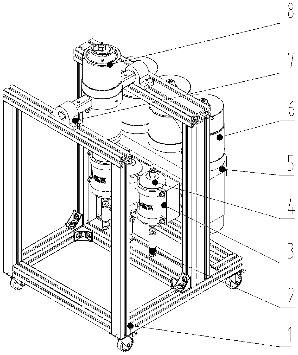
[0040] The present invention aims to provide a high-temperature and high-pressure stirring container with precise injection function, service temperature up to 425°C, and service pressure up to 35MPa. Including: supercritical medium tank, heat isolation component, high temperature and high pressure check valve, piston container, stirring component, auxiliary bracket and so on.

[0041] The application principle of the present invention will be described in detail below in conjunction with the accompanying drawings.

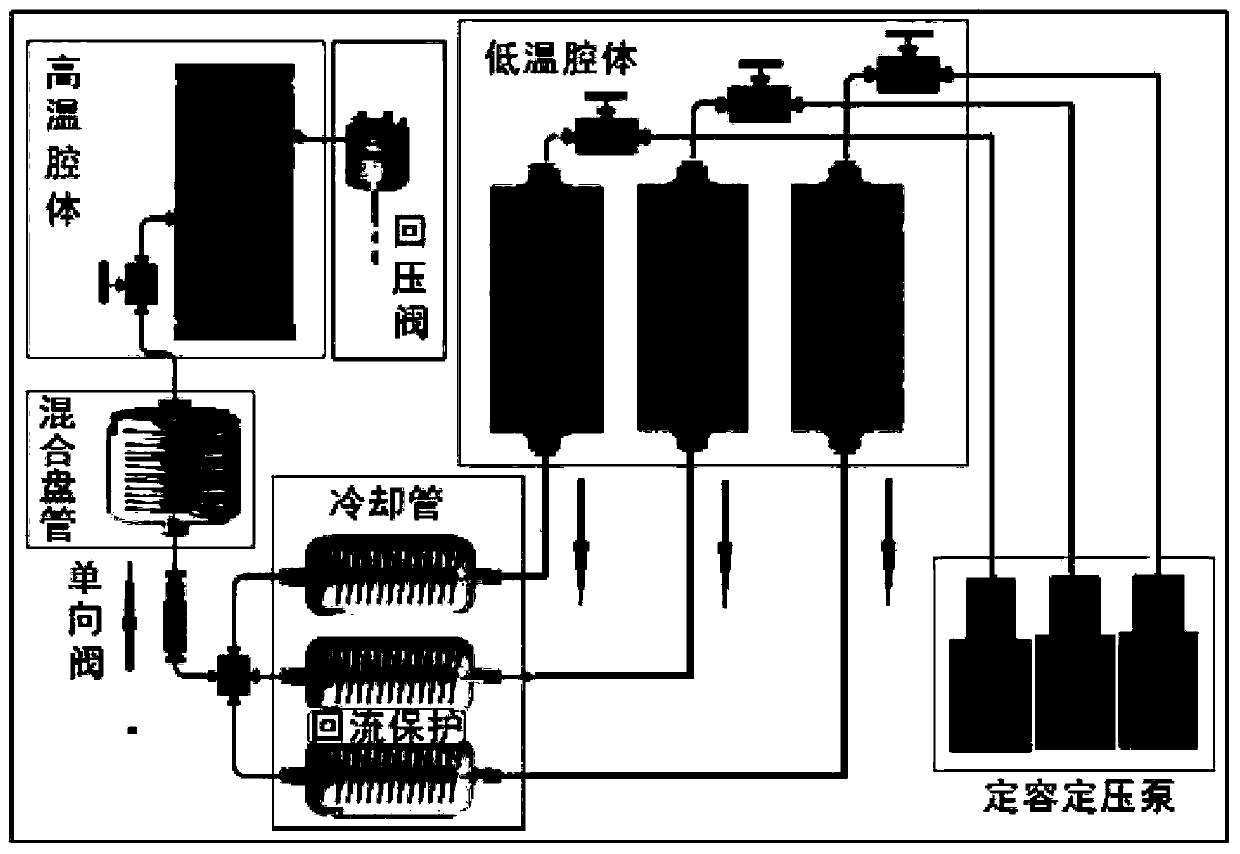
[0042] Such as figure 1 As shown, the multi-component heat flow generation system with injection function ...


PUM


Abstract

The invention belongs to the technical field of petrochemical industry, and discloses a multiple thermal fluid generation system with an injection function and a method of the system. A thermal isolation component is fixed on an aluminum profile support through a thermal isolation component support, a piston container group is fixed on the aluminum profile support through a piston container groupsupport, and a supercritical medium tank is fixed on the aluminum profile support through a stirring component; and the supercritical medium tank is connected with a high-temperature high-pressure one-way valve and the thermal isolation component, and the thermal isolation component is connected with the piston container group. Compared with other stirring containers, the system provided by the invention adopts a segmented temperature-control manner, divides the piston container group and the supercritical medium tank into two different-temperature portions, and ensures reliability of sealingand effectiveness of stirring while satisfying the injection function and the stirring function; and the design of multiple piston containers enables real-time injection of multiple fluid media.

Description

technical field [0001] The invention belongs to the technical field of petrochemical industry, and in particular relates to a multiple heat flow generation system and method with injection function. Background technique [0002] At present, the injection method of the existing multi-element thermal fluid closest to the prior art adopts multiple containers connected in parallel. When the pressure in the container is the same as the pressure of the injected model, different piston containers are opened, and the compressible medium in the piston container The pressure is balanced with the back-end injected model. After the pressure is balanced, open the valves of different piston containers, and inject different fluids into the rear-end model part through depressurization and the injection pump at the lower end of the piston container. This method is prone to pressure crossover. And reflux, while the injection temperature through the piston container is limited, mostly below 25...

Claims


Application Information

Patent Timeline
IPC IPC(8): B01F13/06B01F15/00B01F15/02B01F15/04B01F3/12B01F3/08E21B43/24
CPCE21B43/24B01F23/51B01F23/40B01F23/49B01F23/59B01F33/71B01F35/20B01F35/2215B01F35/71B01F35/80
Inventor 严文德戚志林李继强黄小亮田杰袁迎中
Owner CHONGQING UNIVERSITY OF SCIENCE AND TECHNOLOGY
Why Eureka
Try Eureka