
H-shaped steel and construction method of building with H-shaped steel structure

A technology of H-shaped steel and steel plate, which is applied in building structure, processing of building materials, construction, etc., can solve the problems of easy cracking and deformation of walls and ceilings, difficult connection of corrugated steel plates, and low connection strength of steel structures, etc. Easy to deform and crack, increase connection stability, and have good connection and fixation effects

Active Publication Date: 2019-07-16
NORTH CHINA UNIV OF WATER RESOURCES & ELECTRIC POWER
View PDF6 Cites 0 Cited by
  • Summary
  • Abstract
  • Description
  • Claims
  • Application Information

AI Technical Summary

Problems solved by technology

[0003] Aiming at the deficiencies of the prior art, the present invention provides a construction method for buildings with H-shaped steel and H-shaped steel structures. The purpose is to solve the need to reserve a gap between the shaped steel and the formwork for pouring the wall cavity and filling the gap with other buildings. material, resulting in low strength of the connection between the wall and the section steel, the corrugated steel plate at the bottom of the ceiling is not easy to connect with the wall, the connection strength of the steel structure is low, and the wall and ceiling are easy to crack and deform

Method used


Image

  • H-shaped steel and construction method of building with H-shaped steel structure
  • H-shaped steel and construction method of building with H-shaped steel structure
  • H-shaped steel and construction method of building with H-shaped steel structure

Examples


Embodiment 1

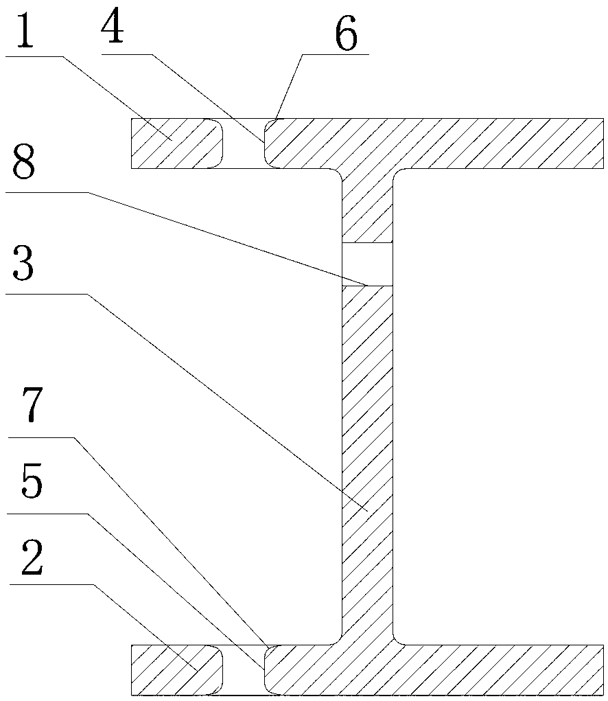
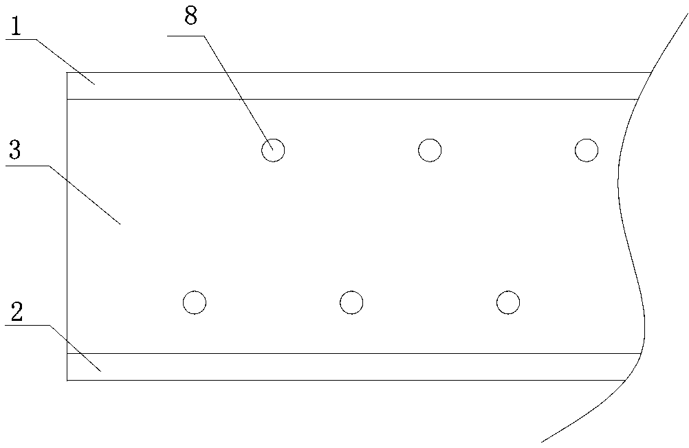
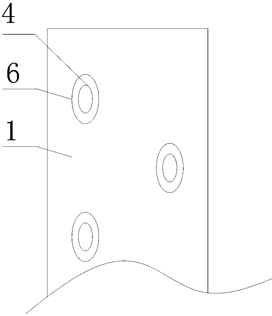
[0038] Example 1, such as Figure 1 to Figure 9 As shown, a kind of H-shaped steel includes an upper wing plate 1, a lower wing plate 2 and a web 3. The upper wing plate 1 and the lower wing plate 2 are horizontal rectangular plates corresponding to each other. The web 3 is a rectangular plate body vertically connecting the center of the lower surface of the upper wing plate 1 and the center of the upper surface of the lower wing plate 2, the upper wing plate 1 is provided with a plurality of first pouring holes 4, the first pouring holes 4 is an elliptical through hole, and a plurality of first pouring holes 4 are staggeredly distributed on the upper wing plate 1 near the left and right sides, and the major axis of the oval cross-section of the first pouring holes 4 is parallel to the On the side, the upper and lower end surfaces of the first pouring hole 4 are respectively provided with a first thinning zone 6 sunken inward, and the first thinning zone 6 is an elliptical con...

Embodiment 2

[0056] Embodiment 2 is basically the same structure as Embodiment 1, the differences, such as Figure 10 As shown, the corrugated steel plate 90 is a continuous "︺"-shaped steel plate. The advantage of this structure is that the continuous "︺"-shaped steel plate is not easily deformed, has better strength and better seismic performance.


PUM


Abstract

The invention relates to H-shaped steel and a construction method of a building with an H-shaped steel structure. The H-shaped steel comprises an upper flange, a lower flange and a web, a first pouring hole is formed in the upper flange, first thinning belts are respectively arranged on the upper end surface and the lower end surface of the first pouring hole, a second pouring hole is formed in the upper surface of the lower flange, second thinning belts are respectively arranged on the upper end surface and the lower end surface of the second pouring hole, staggered circular through holes areformed in the web, the H-shaped steel is used for fixing and tensioning prestressed steel bars, formworks are arranged on two sides of the H-shaped steel, concrete is poured into the first pouring hole and the second pouring hole of the H-shaped steel to form a wall body, a stand column or a ceiling, placing is performed for a period of time for solidification, and finally, a supporting body andthe formworks are disassembled, so that the problems that a gap needs to be reserved between the profile steel and the formworks for pouring a wall cavity, the strength of the joint between the wall and the profile steel is low, and the wall and the ceiling are prone to cracking and deforming are solved.

Description

technical field [0001] The invention relates to the field of building construction, in particular to an H-shaped steel and a construction method for a building with an H-shaped steel structure. Background technique [0002] During the construction of a general steel structure building, first fix the horizontal and vertical section steel, then make beams and columns, and then make the ceiling and wall; when making the wall, it is necessary to install the formwork from the ground to the lower surface of the section steel , There is no pouring hole in the formwork, and a gap needs to be reserved between the steel and the formwork to pour the wall cavity. After the pouring is completed, the gap is filled with other building materials, resulting in low strength at the connection between the wall and the steel , The connection is easy to crack and deform; the corrugated steel plate at the bottom of the ceiling is not easy to connect with the wall, and the connection strength of th...

Claims


Application Information

Patent Timeline
Patent Type & Authority Applications(China)
IPC IPC(8): E04B2/84E04C3/34E04B5/16E04G21/00
CPCE04B2/84E04B5/16E04C3/34E04G21/00
Inventor 郝颖
Owner NORTH CHINA UNIV OF WATER RESOURCES & ELECTRIC POWER
Learn More