A thermal power plant waste heat furnace heat conduction pipe to prevent temperature overflow structure

A technology for thermal power plants and waste heat furnaces, applied to boiler smoke tubes/fire tubes, steam boilers, lighting and heating equipment, etc., can solve the problems of reducing waste heat energy utilization, waste heat energy loss of waste heat furnaces, energy waste, etc., to reduce Waste heat overflow, prevent overflow, improve the effect of heat preservation and heating

Active Publication Date: 2020-05-08
大唐东营发电有限公司
View PDF5 Cites 0 Cited by
  • Summary
  • Abstract
  • Description
  • Claims
  • Application Information

AI Technical Summary

Problems solved by technology

[0003] When the heat conduction pipes in the prior art transport the waste heat energy in the waste heat furnace for a long distance, a large amount of energy is easily wasted, which causes the waste heat energy in the waste heat furnace to be lost in a large range, which greatly reduces the waste heat energy. The utilization rate of the thermal power plant greatly reduces the power generation efficiency of the thermal power plant and causes energy waste, so it cannot meet the needs of the existing technology

Method used


Image

  • A thermal power plant waste heat furnace heat conduction pipe to prevent temperature overflow structure
  • A thermal power plant waste heat furnace heat conduction pipe to prevent temperature overflow structure
  • A thermal power plant waste heat furnace heat conduction pipe to prevent temperature overflow structure

Examples


Embodiment 1

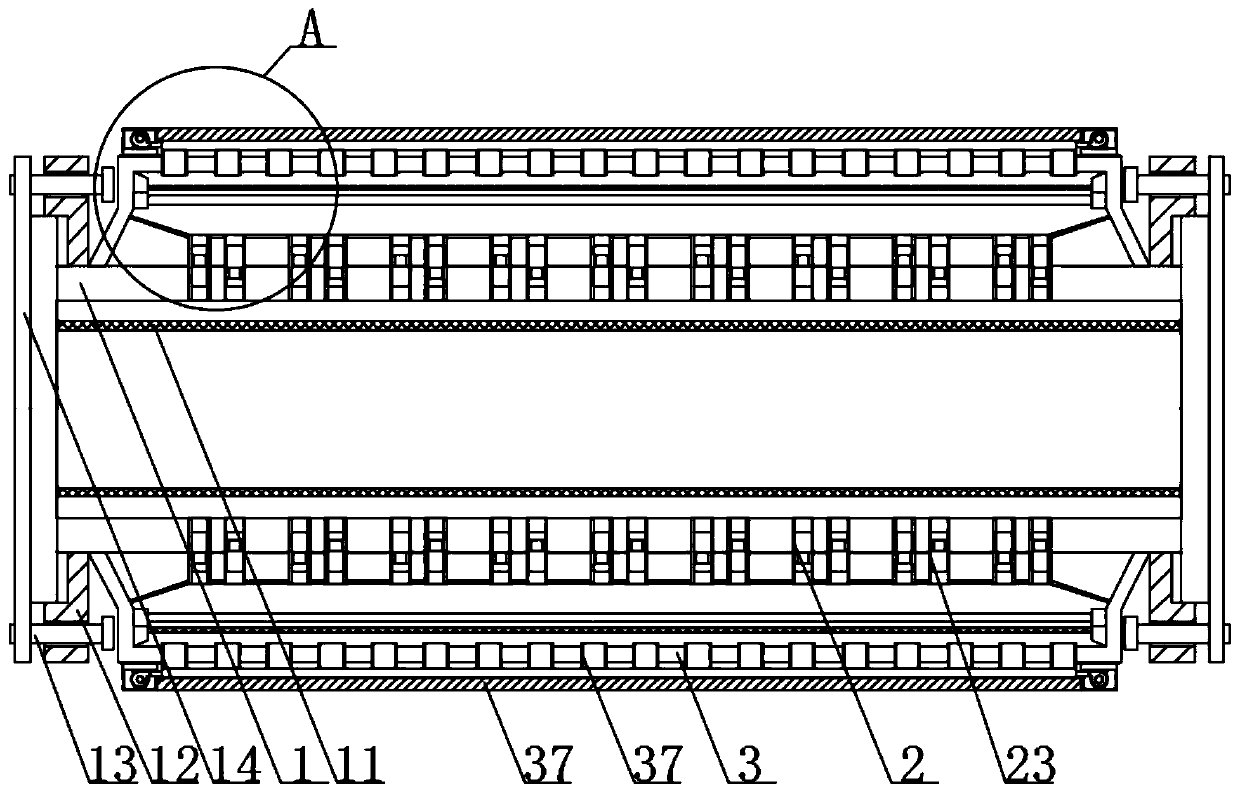
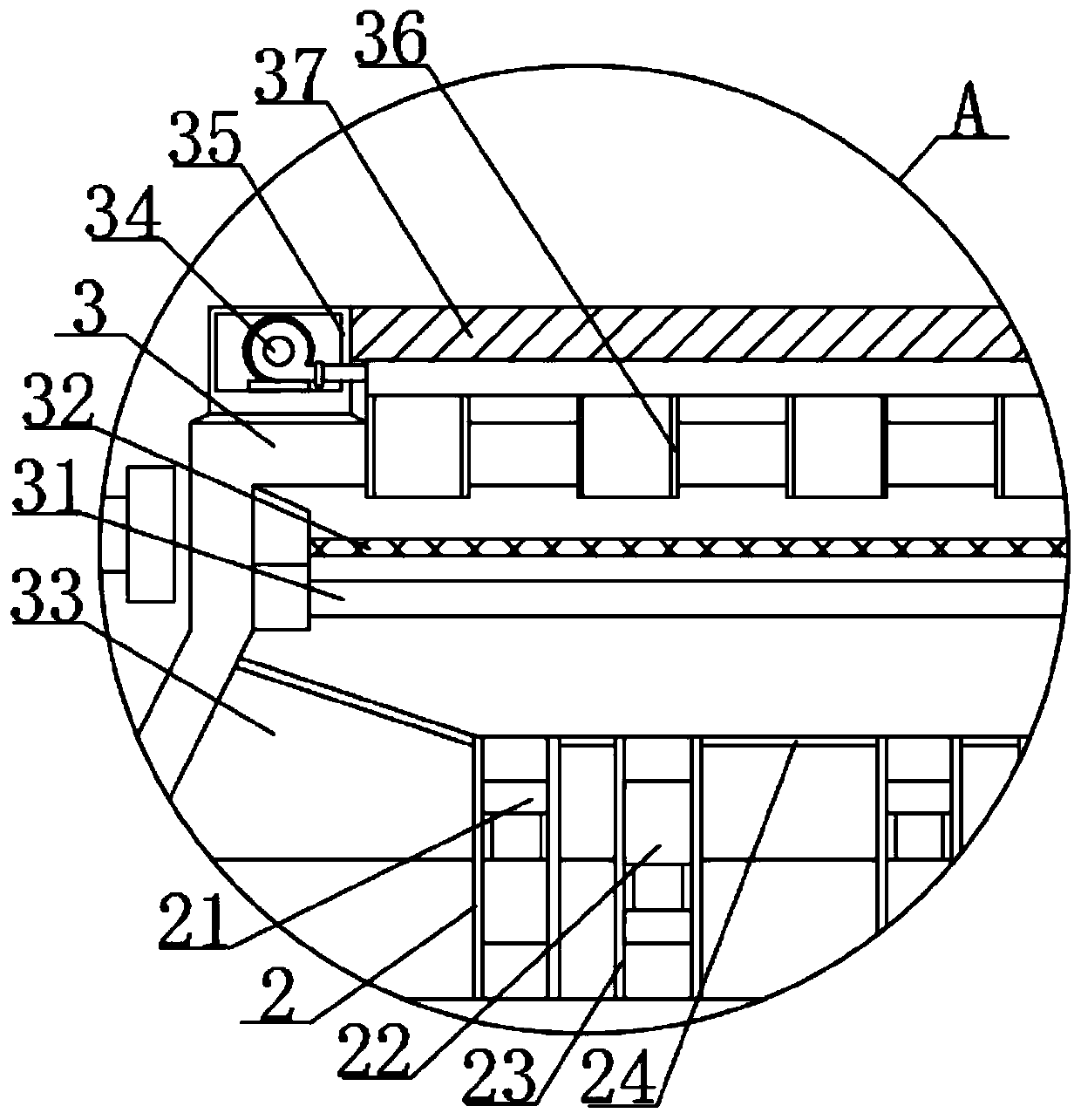
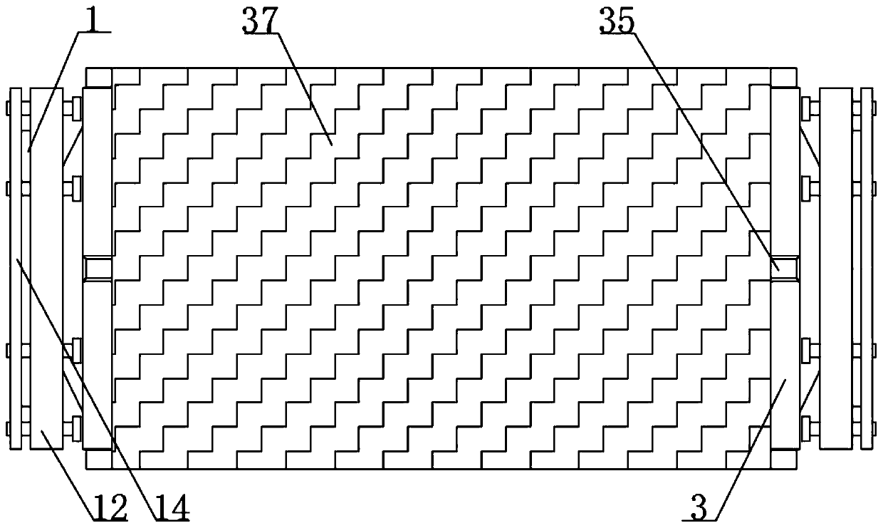
[0026] see Figure 1-5, the present invention provides a technical solution: a structure for preventing temperature overflow of heat conduction pipes for waste heat furnaces in thermal power plants, including a heat conduction pipe body 1; an air intake pipe 2; and a fixed cover 3, and the heat conduction pipe body 1 also includes: a protective net Cover 11, the inner wall of the heat-conducting pipe body 1 is welded with a protective mesh cover 11, and the protective mesh cover 11 is used as a protective device for the heat-conducting pipe body 1, so that the sundries in the gas flowing inside the heat-conducting pipe body 1 are realized Effective blocking, so as to achieve the purpose of placing sundries into the air inlet pipe 2 and the air outlet pipe 23 to cause blockage and reduce the heat conduction effect. There are two fastening frames 12 to facilitate the effective connection of multiple heat-conducting pipe bodies 1 so as to facilitate the heat conduction of waste h...

Embodiment 2

[0028] see figure 1 , figure 2 , image 3 , Figure 4 and Image 6 , the present invention provides a technical solution: a structure for preventing temperature overflow of heat conduction pipes for waste heat furnaces in thermal power plants, including a heat conduction pipe body 1; an air intake pipe 2; and a fixed cover 3, and the heat conduction pipe body 1 also includes: a protective net Cover 11, the inner wall of the heat-conducting pipe body 1 is welded with a protective mesh cover 11, and the protective mesh cover 11 is used as a protective device for the heat-conducting pipe body 1, so that the sundries in the gas flowing inside the heat-conducting pipe body 1 are realized Effective blocking, so as to achieve the purpose of placing sundries into the air inlet pipe 2 and the air outlet pipe 23 to cause blockage and reduce the heat conduction effect. There are two fastening frames 12 to facilitate the effective connection of multiple heat-conducting pipe bodies 1 ...


PUM


Abstract

The invention discloses a temperature overflow preventing structure for a heat conduction pipeline of a waste heat furnace for a thermal power plant. The temperature overflow preventing structure comprises a heat conduction pipeline body, air inlet pipes and a fixing cover, wherein the heat conduction pipeline body further comprises fastening frames. According to the temperature overflow preventing structure, guide covers, the air inlet pipes and air outlet pipes are arranged in the fixing cover, a fan arranged at one side of the fixing cover can effectively realize effective circulation of air between the fixing cover and the heat conduction pipeline body through guide pipes, and meanwhile, through first one-way valves and second one-way valves arranged in the air inlet pipes and the airoutlet pipes correspondingly, air flow between the fixing cover and the heat conduction pipeline body can be directionally channeled so that the air flow in the heat conduction pipeline body can be heated and insulated by electric heating wires arranged in the fixing cover and effective circulation transmission can be carried out at the same time, The effective heat preservation and heating of thewaste heat in the heat conduction pipe body during long-distance transmission are greatly improved and overflow and dispersion are prevented, and the defects in the prior art are made up effectively.

Description

technical field [0001] The invention relates to the technical field of a structure for preventing temperature overflow, in particular to a structure for preventing temperature overflow of a heat conduction pipe for a waste heat furnace in a thermal power plant. Background technique [0002] A thermal power plant, referred to as a thermal power plant, is a factory that uses combustibles (such as coal) as fuel to produce electric energy. Its basic production process is: when the fuel is burned, the water is heated to generate steam, and the chemical energy of the fuel is converted into heat. The steam pressure drives The steam turbine rotates, the thermal energy is converted into mechanical energy, and then the steam turbine drives the generator to rotate, and the mechanical energy is converted into electrical energy. The first-stage flue, the last two-stage flue, the feeding pipe groove, the oxygen gun port, the nitrogen sealing device and the nitrogen sealing plug, the manho...

Claims


Application Information

Patent Timeline
Patent Type & Authority Patents(China)
IPC IPC(8): F22B31/08F22B37/06
CPCF22B31/08F22B37/06
Inventor 贾长武魏厚玉刘士源王清亮周鑫王春良孙振京田乐王颖麟
Owner 大唐东营发电有限公司
Why Eureka
Try Eureka