Battery charging control system

A control system and battery charging technology, applied in battery circuit devices, electric vehicle charging technology, battery data exchange, etc., can solve the problems of easy dust accumulation and inconvenience, and achieve the effect of increasing resistance

Active Publication Date: 2019-07-16
CHONGQING VOCATIONAL INST OF ENG
View PDF9 Cites 0 Cited by
  • Summary
  • Abstract
  • Description
  • Claims
  • Application Information

AI Technical Summary

Problems solved by technology

[0006] The purpose of the present invention is to provide a battery charging control system to solve the problem that dust is easy to accumulate in the charging tank after long-term use, and when charging in the charging tank, if there is no mobile phone support frame, it is very inconvenient to watch videos with the mobile phone

Method used


Image

  • Battery charging control system
  • Battery charging control system
  • Battery charging control system

Examples


Embodiment 1

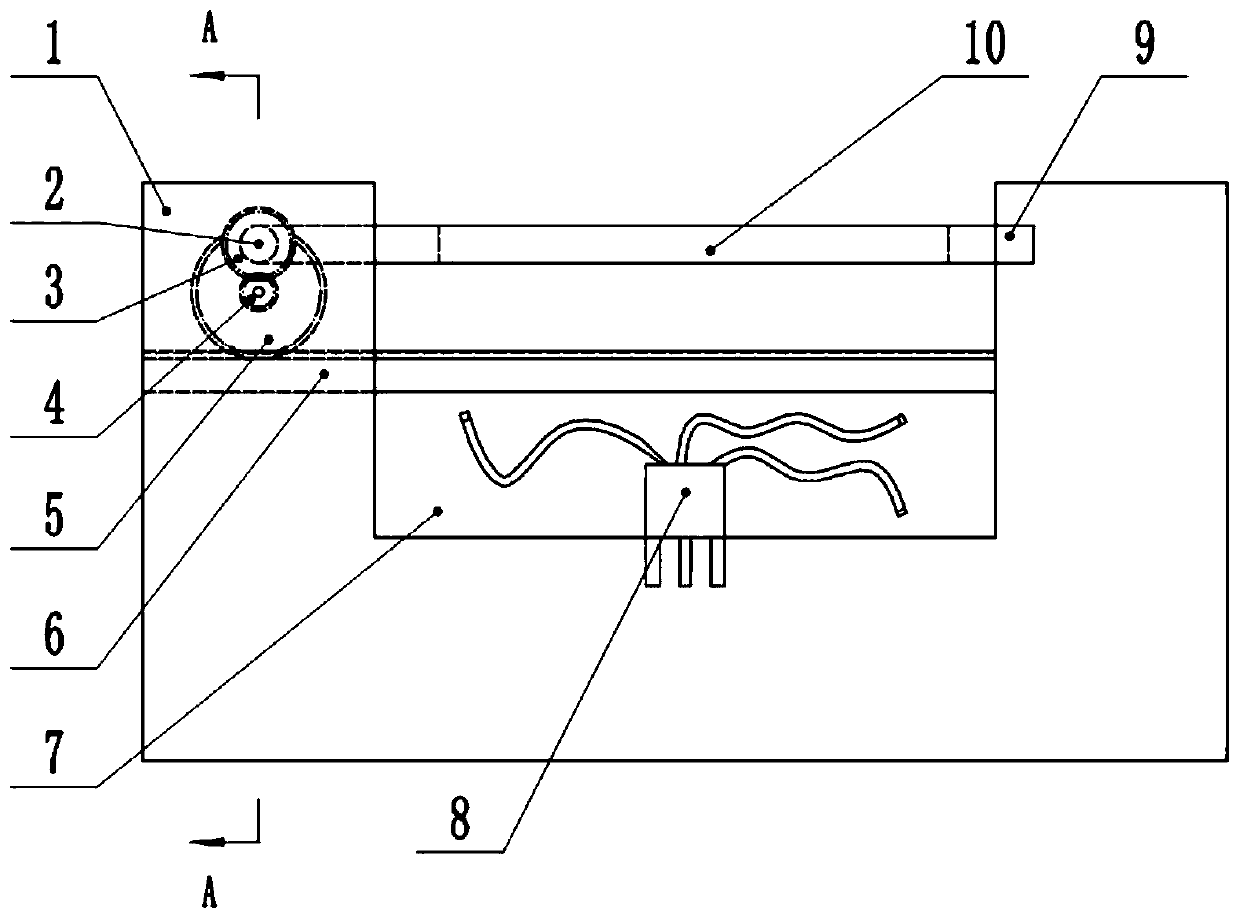
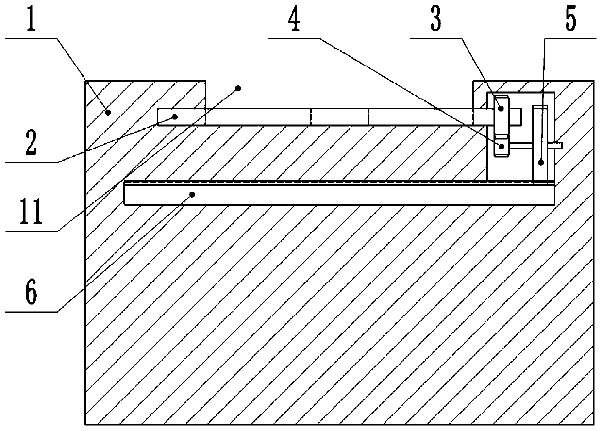
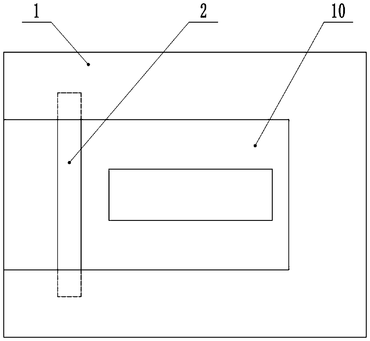
[0061] Embodiment one is basically as attached figure 1 Shown: battery charging control system, including server, mobile phone terminal, controller, charging device 1 and transmission device, transmission device includes driving gear 3, driven gear 4 and transmission gear 5, the diameter of transmission gear 5 is larger than that of driving gear 3 diameter, the diameter of the driving gear 3 is greater than the diameter of the driven gear 4, and the server includes an acquisition module, a database, a statistics module and a push module.

[0062] The charging device 1 has a charging slot 7 from top to bottom, and the bottom of the charging slot 7 is a socket electrically connected to the power supply and a charger 8 for charging the mobile phone. The plug end of the charger 8 is inserted into the socket, and the plug is connected to the plug by a screw. The charger 8 is fixed on the socket, and one end of the charger 8 connected with the data line is used to be connected with ...

Embodiment 2

[0077] Such as Figure 5 As shown, the difference between the second embodiment and the first embodiment is that the server further includes a payment information sending module, and the mobile terminal includes a payment confirmation module and a deduction module.

[0078] The obtaining module is used to obtain the successful scanning information sent from the mobile phone when the mobile phone successfully scans the QR code.

[0079] The payment information sending module is used to send the payment information to the mobile terminal when the acquisition module obtains the scanning success information.

[0080] The payment confirmation module is used for the user to confirm whether to pay when the mobile terminal receives the payment information, and to generate mobile payment confirmation information after confirming the payment.

[0081] The deduction module is used to receive mobile phone payment confirmation information, and deduct the charging fee when receiving the mo...

Embodiment 3

[0085] Such as Figure 6 As shown, the difference between the third embodiment and the second embodiment is: the controller, the acquisition module and the deduction module, and also includes a relay, and the server also includes a calculation module, a judgment module and a power failure information sending module, and the relay is electrically connected It is on the power supply circuit of the socket and the power supply, and the controller is electrically connected with the relay.

[0086] The obtaining module is also used to obtain the power information and charging status information of the mobile terminal.

[0087] The judging module is used to judge whether the power of the mobile phone is full according to the power information, and when it is full, sends the charging completion information to the power-off information sending module, and the judging module is also used to judge whether the mobile terminal is in a charging state according to the charging status informa...


PUM


Abstract

The invention relates to the technical field of battery charging, in particular to a battery charging control system. The battery charging control system comprises a controller and a charging device,wherein a charging groove is formed in the charging device, a socket and a charger are arranged in the charging groove, a groove is formed in a left side wall of the charging groove, a rotation shaftis arranged in the groove, a rotation plate is connected with a columnar surface of the rotation shaft, a first through groove is formed in the rotation plate, the other end, far away from the rotation shaft, of the rotation plate is contacted with a right side wall of the charging groove, a solenoid valve is arranged at a contact position and is used for absorbing the rotation plate, the solenoidvalve is electrically connected with the controller, a second through groove is formed in a left side wall of the charging groove, a shielding plate is connected to the second through groove in a sliding way and is used for shielding the charging groove, an accommodating cavity is formed in the second through groove, a transmission device is arranged on the accommodating cavity and is used for driving the shielding plate to leftwards and rightwards slide, and the transmission device is driven by the rotation shaft. Therefore, the problems that dust is easily accumulated in the charging grooveand a mobile phone is handheld to watch and is not very convenient during charging if no mobile phone support rack is arranged are solved, and the battery charging control system is mainly used for apublic occasion such as a shopping mall.

Description

technical field [0001] The invention relates to the technical field of battery charging, in particular to a battery charging control system. Background technique [0002] With the rapid development of mobile communication technology, fast charging terminals led by smart phones and tablet computers gradually occupy a large share in the terminal equipment market. And with the development of terminal devices such as smartphones and tablet computers, the processing speed of the central processing unit (CPU) is also gradually increasing, which leads to a sharp increase in the power consumption rate of the internal battery of the terminal device. In order not to affect the standby time As time goes by, the battery capacity of the terminal device will inevitably increase gradually. [0003] Although the battery capacity of these terminal devices has been expanded and the charging efficiency has been improved, overcharging often occurs when the battery is being charged. A fully ch...

Claims


Application Information

Patent Timeline
IPC IPC(8): H02J7/00G07F15/00
CPCH02J7/0027H02J7/0042H02J7/0044H02J7/0013G07F15/006H02J7/00036H02J7/00034Y02T90/12
Inventor 胡银全范奇恒詹善兵谭亚红
Owner CHONGQING VOCATIONAL INST OF ENG
Why Eureka
Try Eureka