
A Position Sensorless Control Method for Permanent Magnet Synchronous Motor Based on High Frequency Signal Injection

A permanent magnet synchronous motor, high-frequency signal technology, applied in motor generator control, electronic commutation motor control, control system and other directions, can solve problems such as reducing system control performance

Active Publication Date: 2020-11-03
SOUTHEAST UNIV
View PDF3 Cites 0 Cited by
  • Summary
  • Abstract
  • Description
  • Claims
  • Application Information

AI Technical Summary

Problems solved by technology

Therefore, the high-frequency current of the d-axis response will generate high-frequency electromagnetic torque ripple, which will reduce the control performance of the system

Method used


Image

  • A Position Sensorless Control Method for Permanent Magnet Synchronous Motor Based on High Frequency Signal Injection
  • A Position Sensorless Control Method for Permanent Magnet Synchronous Motor Based on High Frequency Signal Injection
  • A Position Sensorless Control Method for Permanent Magnet Synchronous Motor Based on High Frequency Signal Injection

Examples


Embodiment Construction

[0046] The present invention will be further explained below in conjunction with the drawings.

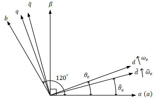
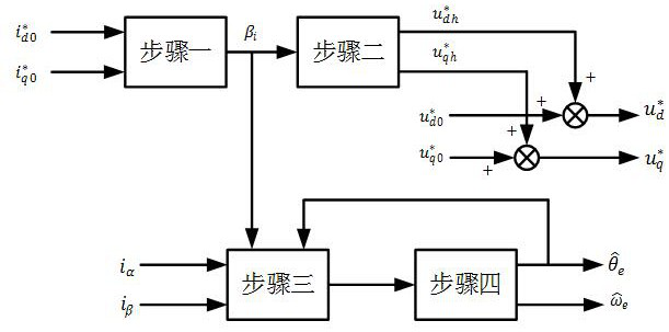
[0047] The basic idea of ​​the present invention is to obtain the optimal high-frequency current angle and the optimal high-frequency voltage angle based on the principle of minimizing the electromagnetic torque high-frequency ripple when distributing the high-frequency voltage components injected by the d-axis and the q-axis; When calculating the rotor position estimation value, the high frequency current component of the control response is 0 at the orthogonal position of the optimal high frequency current angle, so that the rotor position estimation value error is 0, so as to obtain an accurate rotor position estimation value.

[0048] 1. Basic principle description

[0049] 1. Permanent magnet synchronous motor voltage equation and coordinate transformation

[0050] The mathematical model of the permanent magnet synchronous motor can be written in matrix form or complex vector form. Fo...


PUM


Abstract

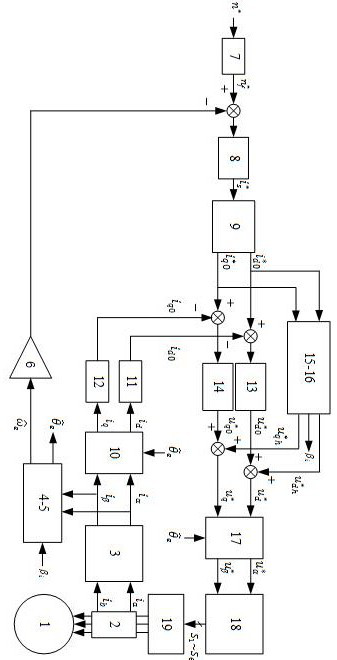
The invention discloses a permanent magnet synchronous motor sensorless control method based on high-frequency signal injection. Due to the existence of the magnetic resistance torque of an interior permanent magnet synchronous motor, when a sensorless algorithm based on traditional high-frequency pulse vibration voltage signal injection is adopted, electromagnetic torque high-frequency pulsationis generated, especially in a control method when the non-id is equal to 0, the high-frequency pulsation of the electromagnetic torque is more obvious. When the injected d-axis and q-axis high-frequency voltage components are distributed, the minimum electromagnetic torque high-frequency pulsation is taken as the principle, the optimal high-frequency current angle and the optimal high-frequency voltage angle are obtained according to a torque formula, and the most appropriate high-frequency voltage injection direction is selected; when a rotor position estimation value is calculated, the responded high-frequency current component is controlled to be zero at the orthogonal position of the optimal high-frequency current angle, so that the error of the rotor position estimation value is zero,and an accurate rotor position estimation value is obtained. According to the method, the electromagnetic torque high-frequency pulsation caused by high-frequency signal injection can be effectivelyreduced, so that the performance of a sensorless control system is improved.

Description

Technical field [0001] The invention belongs to the field of motor driving and control, and in particular relates to a position sensorless control system of a permanent magnet synchronous motor based on high-frequency signal injection. Background technique [0002] High-performance speed control of permanent magnet synchronous motors generally requires position sensors, such as rotary encoders and photoelectric encoders. The installation position sensor not only has high cost, large size, and low mechanical reliability, but also brings about concentricity problems during installation. The use of a highly reliable position sensorless control algorithm is an effective solution. [0003] When a permanent magnet synchronous motor is running at zero or low speed, it often uses a high-frequency voltage signal injection algorithm based on the motor's salient pole effect, which can inject different forms of voltage signals in different reference coordinate systems. In recent years, the mo...

Claims


Application Information

Patent Timeline
Patent Type & Authority Patents(China)
IPC IPC(8): H02P21/24H02P21/18H02P6/10
CPCH02P6/10H02P21/18H02P21/24
Inventor 花为唐爱慧王益
Owner SOUTHEAST UNIV
Learn More