Spinning device for 1414 yarn and preparation method thereof
A technology of equipment and yarn, applied in the field of spinning equipment and preparation of 1414 yarn, can solve the problems of inability to reduce the stiffness of the yarn, poor electrostatic removal effect, etc. The effect of static electricity
- Summary
- Abstract
- Description
- Claims
- Application Information
AI Technical Summary
Problems solved by technology
Method used
Image
Examples
preparation example Construction
[0052]A preparation method for the spinning equipment of the above-mentioned 1414 yarn, the preparation method includes the following steps: the cotton layer 1 output in the cotton box 11 first passes through the cotton feeding roller 13, the inclined supporting plate 15, and the cotton feeding roller 14 successively Enter the carding machine 12, then go through the licker-in roller 121, the cylinder 122, the doffer 123, and then enter the sliver can 61 to obtain the sliver 6, and then the sliver 6 is output from the exit of the sliver can 61, and then goes through the guide sliver in turn. Roller 62, horizontal supporting plate 16, and feeding roller 63 enter the drawing frame to generate raw sliver, and the bottom surface of the cotton layer 1 is in contact with the top surface of the inclined supporting plate 15, and the bottom surface of the cotton sliver 6 is in contact with the top surface of the horizontal supporting plate 16. contact with the top surface;
[0053] When...
Embodiment 1
[0062] see figure 1 - Figure 9 , a kind of spinning equipment of 1414 yarns, comprising a cotton box 11, a carding machine 12, a sliver can 61 and a cotton feeding roller 63, and the carding machine 12 comprises a licker-in roller 121, a cylinder 122 and a doffer 123, the The outlet of the cotton box 11 communicates with the entrance of the sliver can 61 after passing through the cotton feeding roller 13, the cotton feeding roller 14, the licker-in roller 121, the cylinder 122, and the doffer 123 successively, and the exit of the cotton sliver can 61 passes through the guide roller 62 successively. 1. After feeding the cotton roller 63, it communicates with the draw frame; the cotton feeding roller 13 communicates with the cotton feeding roller 14 through the inclined pallet 15, and the angle between the inclined pallet 15 and the horizontal plane is an acute angle, and the top of the inclined pallet 15 An inclined pressing plate 19 parallel to it is provided, and a pluralit...
Embodiment 2
[0065] Basic content is the same as embodiment 1, the difference is:
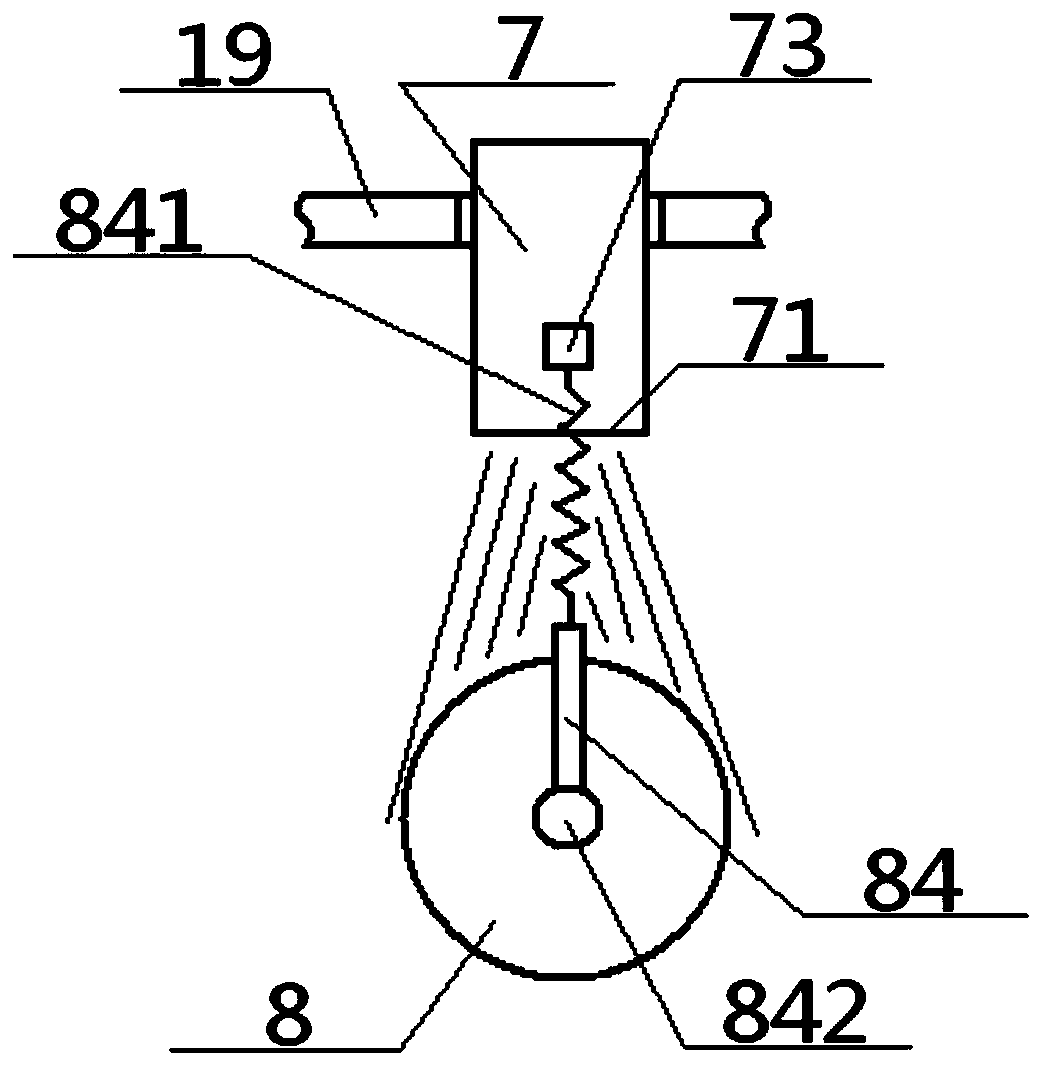
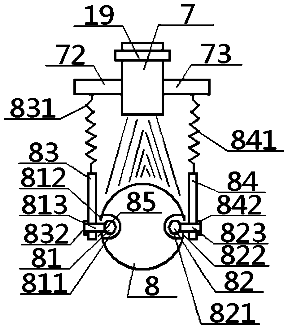
[0066] Structurally: the top of the inclined spray head 7 is connected to the inclined pressure plate 19, the middle part of the inclined spray head 7 is connected to the inner ends of the left hanging column 72 and the right hanging column 73, and the bottom of the inclined spray head 7 is an air outlet nozzle 71, the air outlet Just below the mouth 71 is provided with a shunt rolling ball 8, which is provided with a left rolling chamber 811 and a right rolling chamber 821 facing each other. The left rolling chamber 811 and the right rolling chamber 821 are each provided with a corresponding left Ball 81, right rolling ball 82, said left rolling ball 81 passes through left rolling chamber 811, left cavity mouth 812, left horizontal shaft 813 in turn and is fixedly connected with the bottom end of left column 83, and the top of left column 83 stretches through the left The belt 831 is connected with the out...
PUM
 Abstract
Description
Claims
Application Information
 - R&D
- Intellectual Property
- Life Sciences
- Materials
- Tech Scout
- Unparalleled Data Quality
- Higher Quality Content
- 60% Fewer Hallucinations
Browse by: Latest US Patents, China's latest patents, Technical Efficacy Thesaurus, Application Domain, Technology Topic, Popular Technical Reports.
© 2025 PatSnap. All rights reserved.Legal|Privacy policy|Modern Slavery Act Transparency Statement|Sitemap|About US| Contact US: help@patsnap.com


