Bridge damping expansion joint

A technology of expansion joints and bridges, applied in bridges, bridge parts, bridge construction, etc., can solve problems such as shock absorption performance discount, spring performance drop, driving safety accidents, etc., to achieve the effect of ensuring stability and avoiding detachment

Active Publication Date: 2019-07-19
广东德利路桥装备科技有限公司
View PDF9 Cites 2 Cited by
  • Summary
  • Abstract
  • Description
  • Claims
  • Application Information

AI Technical Summary

Problems solved by technology

Once the telescopic device of the skew bridge is damaged, it will seriously affect the speed, comfort and safety of driving, and even cause driving safety accidents
[0003] Most of the structures of current bridge expansion joints adopt the damping structure directly connected by springs, such as Chinese Patent Announcement No. CN208201627U "A Damping Device for Bridge Expansion Joints" and

Method used


Image

  • Bridge damping expansion joint
  • Bridge damping expansion joint
  • Bridge damping expansion joint

Examples


Embodiment 1

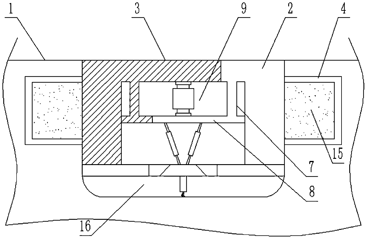
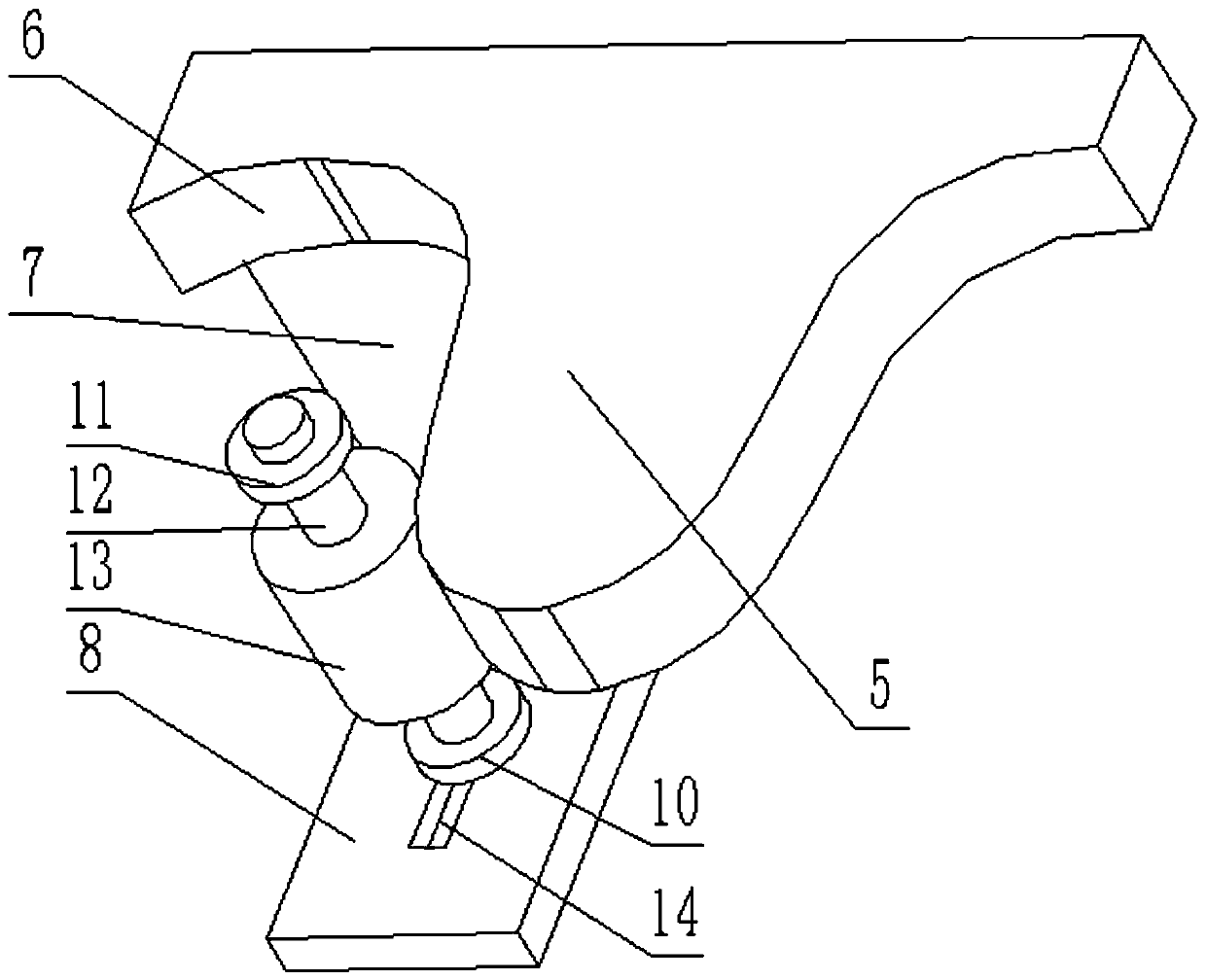
[0019] see Figure 1-3 , a bridge shock-absorbing expansion joint, including a square groove-shaped seam body and a buffer shock-absorbing structure located in the seam body, the buffer shock-absorbing structure includes a right corrugated frame 2 and a left corrugated frame 3 located on both sides of the seam body, and the right corrugated frame 2 and the left corrugated frame 3 have the same shape and structure and are staggered on the same horizontal plane. The upper plane of the corrugated frame is flush with the top surface of the bridge body 1. Protrusions 5 and depressions 6 are arranged at intervals. The protrusions 5 are used to insert into the depressions 6 on the opposite corrugated frame, so as to maintain the stability of the seam structure when the seam is deformed. The front end of the protrusions 5 and the depression The tail ends of the parts 6 are all arc-shaped, and a parallel plate 8 arranged parallel to the protruding part 5 is arranged below the concave p...

Embodiment 2

[0022] On the basis of Example 1, the steel bar 4 is sealed and docked with the back of the corrugated frame to form a "mouth"-shaped cavity, and the cavity is filled with sound-absorbing cotton 15. The collision produces vibration, and the vibration is transmitted to the sound-absorbing cotton 15 through the corrugated frame and the steel bar 4, and the sound-absorbing cotton 15 eliminates the noise generated by the vibration, and then also plays a certain elimination effect on the vibration.

Embodiment 3

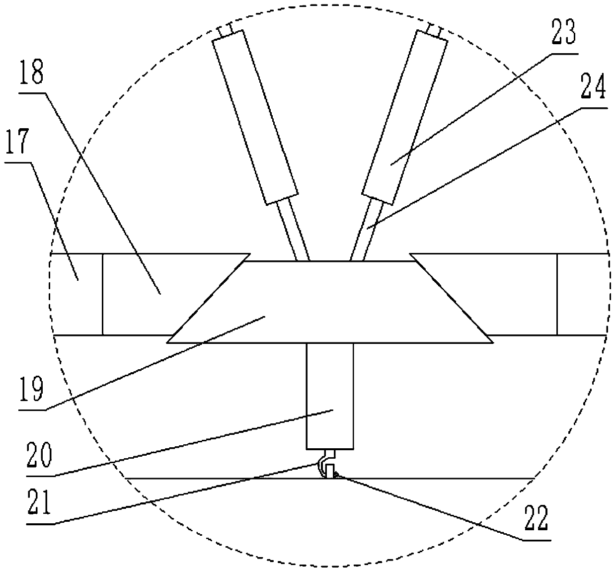
[0024] On the basis of Example 1, there is a gap between the vertical plate 7 and the corresponding vertical surface of the corrugated frame, and the side of the parallel plate 8 at the bottom of the vertical plate 7 is attached to the vertical surface of the corrugated frame and is not fixed. This design ensures that the parallel plate 8 can vibrate differently from the corrugated frame when it is vibrated, so as to avoid the resonance effect of the buffer and shock-absorbing structure, thereby further improving the safety of the overall device and the bridge body 1.


PUM


Abstract

The invention discloses a bridge damping expansion joint. The bridge damping expansion joint comprises a square-groove-shaped joint body and a cushioning and damping structure located in the joint body, the cushioning and damping structure comprises a right corrugated rack and a left corrugated rack which are located on two sides in the joint body, the right corrugated rack and the left corrugatedrack have the same shape and structure and are arranged on a same horizontal plane in a staggered mode, upper surfaces of the corrugated racks are flush with a top surface of a bridge body, and the corrugated racks are provided with steel bar rods embedded in the bridge body; and convex parts and concave parts arranged at intervals are arranged at the tops of the corrugated racks, the front endsof the convex parts and the tail ends of the concave parts are all in a circular arc shape, and paralleled plates arranged in parallel with the convex parts are arranged under the concave parts. According to the bridge damping expansion joint, through the following movement of a damper, a stable state is kept when the joint body is contracted and stretched because of cold and hot effects, the damper is different from a regular single-type spring damping, when the distance of the joint body is changed because of temperature, the relative stability of the self length of spring can be kept, and the damping performance of the damper cannot be influenced due to long-time stretching and contraction, and the long time effectiveness of the cushioning and damping structure is guaranteed.

Description

technical field [0001] The invention relates to bridge highway facilities, in particular to a bridge damping expansion joint. Background technique [0002] Bridge expansion joints refer to expansion joints usually set between two girder ends, between girder ends and abutments, or at the hinged position of the bridge in order to meet the deformation requirements of the bridge deck. It is required that the expansion joints can freely expand and contract in two directions parallel to and perpendicular to the bridge axis, and are firm and reliable. The vehicles should run smoothly without sudden jumps and noises; they should be able to prevent rainwater and garbage from infiltrating and blocking; installation, inspection, and maintenance , Elimination of dirt should be simple and convenient. Where expansion joints are set, railings and bridge deck pavement must be disconnected. The function of bridge expansion joints is to adjust the displacement and connection between the sup...

Claims


Application Information

Patent Timeline
IPC IPC(8): E01D19/06
CPCE01D19/06
Inventor 孙虎杜祝遥王振峰何佳郭户林
Owner 广东德利路桥装备科技有限公司
Why Eureka
Try Eureka