Automobile exhaust waste heat recycling system

A waste heat recovery and vehicle exhaust technology, applied in heat exchangers, exhaust devices, indirect heat exchangers, etc., can solve problems such as large technical difficulties and limited space for improvement

Pending Publication Date: 2019-07-19
JAPHL POWERTRAIN SYST
View PDF0 Cites 1 Cited by
  • Summary
  • Abstract
  • Description
  • Claims
  • Application Information

AI Technical Summary

Problems solved by technology

Improving the thermal efficiency of the engine body is a technical route, but there are great technical difficulties and the room for improvement is very limited

Method used


Image

  • Automobile exhaust waste heat recycling system
  • Automobile exhaust waste heat recycling system
  • Automobile exhaust waste heat recycling system

Examples


Embodiment Construction

[0022] Below with reference to the accompanying drawings, through the description of the embodiments, the specific embodiments of the present invention, such as the shape, structure, mutual position and connection relationship between the various parts, the role and working principle of the various parts, etc., will be further described. Detailed instructions:

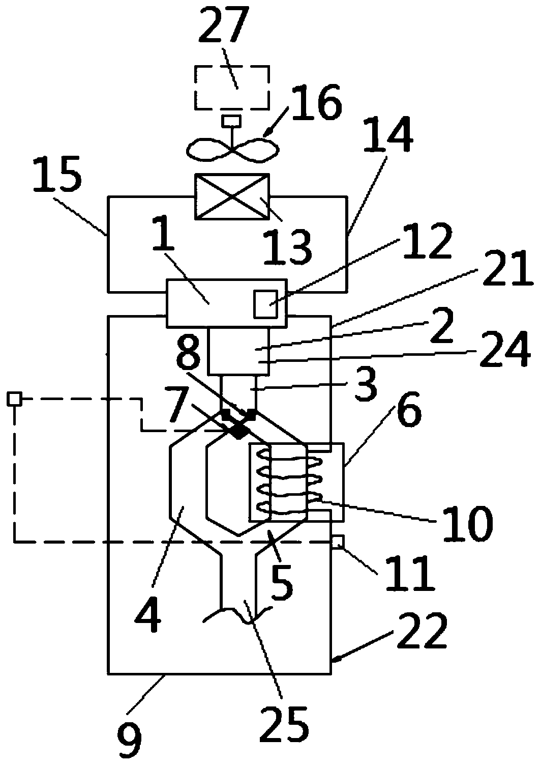
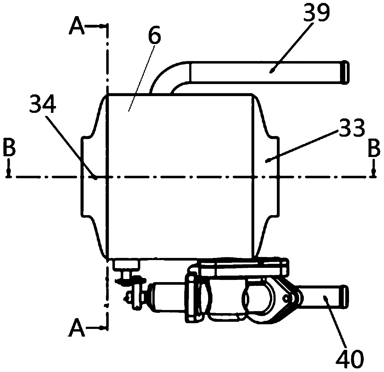
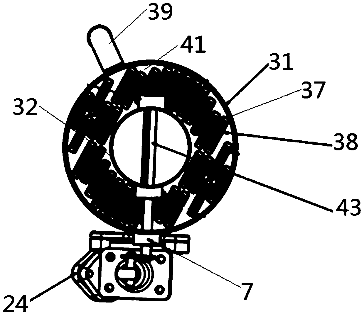
[0023] as attached figure 1 - attached Figure 4 As shown, the present invention is a system for recovering and reusing waste heat from automobile exhaust. The system for reusing and reusing waste heat from automobile exhaust includes an engine body 1, an exhaust manifold 2, and an exhaust pipe 3. The exhaust pipe 3 includes Exhaust pipe branch line I4 and exhaust pipe branch line II5, exhaust pipe branch line II5 is provided with heat exchanger 6, exhaust pipe 3 is provided with bypass valve actuator 7 and bypass valve 8, bypass The through valve actuator 7 is arranged as a structure capable of controlling the movemen...


PUM


Abstract

The invention provides an automobile exhaust waste heat recycling system applied in the technical field of automobile engines. A front end plate (35) is arranged at the position, close to an inlet cone end (33), between an outer layer shell (31) and an inner layer shell (32) of a heat exchanger (6) of the automobile exhaust waste heat recycling system; a rear end plate (36) is arranged at the position, close to an outlet cone end (34), between the outer layer shell (31) and the inner layer shell (32); a plurality of flat tubes (37) are inserted between the front end plate (35) and the rear endplate (36); fins (38) are inserted in each flat tube (37) separately; and a gap part is formed between each flat tube (37) and the fin (38) inserted in the flat tube (37). The automobile exhaust heatrecycling system can recover part of the heat from automobile exhaust when an automobile is cold-started, and then utilize the heat to heat a coolant in an automobile engine cooling system so as to quickly and reliably warm an engine and improve the thermal efficiency of the engine during cold-start.

Description

technical field [0001] The invention belongs to the technical field of automobile engines, and more specifically relates to a system for recovering and reusing waste heat from automobile exhaust. Background technique [0002] With the global energy situation becoming more and more tense, environmental protection becoming more and more urgent, and the number of cars in various countries in the world continues to rise, traditional fuel vehicles and hybrid vehicles are facing huge pressure on energy conservation and emission reduction. For traditional automobile engines, the water temperature in the engine water jacket is low during cold start. At this time, the lubrication effect of the various parts of the engine is poor, the friction force is large, and the thermal efficiency is low. At this time, the combustion in the cylinder is relatively insufficient, so The production and emission of harmful gases are relatively high. At present, there is no good way to improve the ther...

Claims


Application Information

Patent Timeline
Patent Type & Authority Applications(China)
IPC IPC(8): F01N5/02F02N19/10F01N13/08F28D21/00F28F27/00F16K1/22F16K31/64F16K37/00
CPCF01N5/02F01N13/08F02N19/10F16K1/22F16K31/002F16K37/0091F28D21/0003F28F27/00Y02T10/12
Inventor 杨健春严清梅李后良姜倩范礼于芳
Owner JAPHL POWERTRAIN SYST
Why Eureka
Try Eureka