Furnace end lining structure for combustion furnace of sulfur recovery unit

A combustion furnace, sulfur recovery technology, applied in the direction of the overall lining, furnace, furnace components, etc., can solve the problems of short life of the refractory lining, unreasonable lining structure of the furnace head, overheating of the furnace head, etc., to achieve enhanced containment, Reasonable structural design, reducing the effect of expansion joints

Pending Publication Date: 2019-07-19
无锡市亿洲耐火材料有限公司
View PDF1 Cites 1 Cited by
  • Summary
  • Abstract
  • Description
  • Claims
  • Application Information

AI Technical Summary

Problems solved by technology

[0004] The technical problem to be solved by the present invention is to overcome the deficiencies of the prior art, solve the problem of unreasonable structure of the furnace head lining of the combustion furnace of the sulfur recovery device in the past, the frequent overtemperature of the furnace head, and the short service life of the refractory lining, and provide a furnace The head lining structure design is reasonable, a kind of sulfur recovery device combustion furnace head lining structure with high firmness

Method used


Image

  • Furnace end lining structure for combustion furnace of sulfur recovery unit
  • Furnace end lining structure for combustion furnace of sulfur recovery unit
  • Furnace end lining structure for combustion furnace of sulfur recovery unit

Examples


Embodiment Construction

[0023] In order to make the technical problems, technical solutions and beneficial effects to be solved by the present invention clearer, the present invention will be further described in detail below in conjunction with the accompanying drawings and embodiments. It should be understood that the specific embodiments described here are only used to explain the present invention, not to limit the present invention.

[0024] It should be noted that when an element is referred to as being “fixed on” or “disposed on” another element, it may be directly on the other element or be indirectly on the other element. When an element is referred to as being "connected to" another element, it can be directly connected to the other element or indirectly connected to the other element.

[0025] It is to be understood that the terms "length", "width", "top", "bottom", "front", "rear", "left", "right", "vertical", "horizontal", "top" , "bottom", "inner", "outer" and other indicated orientati...


PUM


Abstract

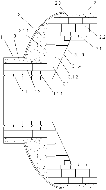
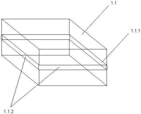
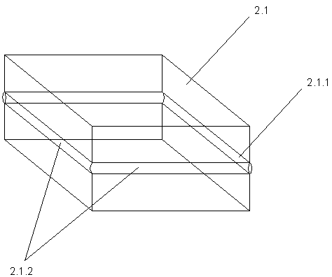
The invention discloses a furnace end lining structure for a combustion furnace of a sulfur recovery unit. The furnace end lining structure mainly comprises a furnace opening section lining structure,a straight barrel section lining structure and a transition section lining structure which is connected with a furnace opening section and a straight barrel section. The furnace opening section lining structure is sequentially provided with furnace opening section refractory bricks, furnace opening section insulating bricks and a furnace opening section castable layer from inside to outside. Thestraight barrel section lining structure is sequentially provided with straight barrel section refractory bricks, straight barrel section insulating bricks and a straight barrel section castable layerfrom inside to outside. The transition section lining structure is mainly formed by splicing a plurality of special-shaped refractory bricks. The furnace end lining structure is reasonable in designand high in firmness.

Description

technical field [0001] The invention relates to the field of sulfur recovery equipment, in particular to a lining structure of a combustion furnace head of a sulfur recovery device. Background technique [0002] The combustion furnace of the sulfur recovery unit is one of the core equipment of the sulfur recovery unit. The designed operating temperature of the combustion furnace is about 1450°C. The lining of the combustion furnace head of the traditional sulfur recovery unit generally adopts a castable structure or a simple brick structure. The material structure is easy to crack and peel off, and a large number of holes are concentrated in the furnace head, which makes the construction difficult; while the simple brick structure is easy to produce large expansion joints in the furnace head, causing the outer wall temperature to be too high or even burn through. [0003] Chinese patent CN203881138U discloses a refractory lining for the main combustion furnace of a sulfur re...

Claims


Application Information

Patent Timeline
Patent Type & Authority Applications(China)
IPC IPC(8): F27D1/10F27D1/04
CPCF27D1/04F27D1/10
Inventor 钱强徐建明徐达曹彪朱新强储佳平潘越吴雯扬
Owner 无锡市亿洲耐火材料有限公司
Why Eureka
Try Eureka