Punching abrasion testing device based on control energy

A wear test and energy technology, which is used in measuring devices, testing wear resistance, and testing material strength by applying repetitive force/pulse force. , to achieve the effect of enhancing practicability and improving test accuracy

Active Publication Date: 2019-07-19
SOUTHWEST JIAOTONG UNIV
View PDF6 Cites 4 Cited by
  • Summary
  • Abstract
  • Description
  • Claims
  • Application Information

AI Technical Summary

Problems solved by technology

[0004] The purpose of the present invention is to provide a punching wear test device based on energy control, which solves the problem that the existing impact wear test machine has a low degree of automatio

Method used


Image

  • Punching abrasion testing device based on control energy
  • Punching abrasion testing device based on control energy
  • Punching abrasion testing device based on control energy

Examples


Embodiment 1

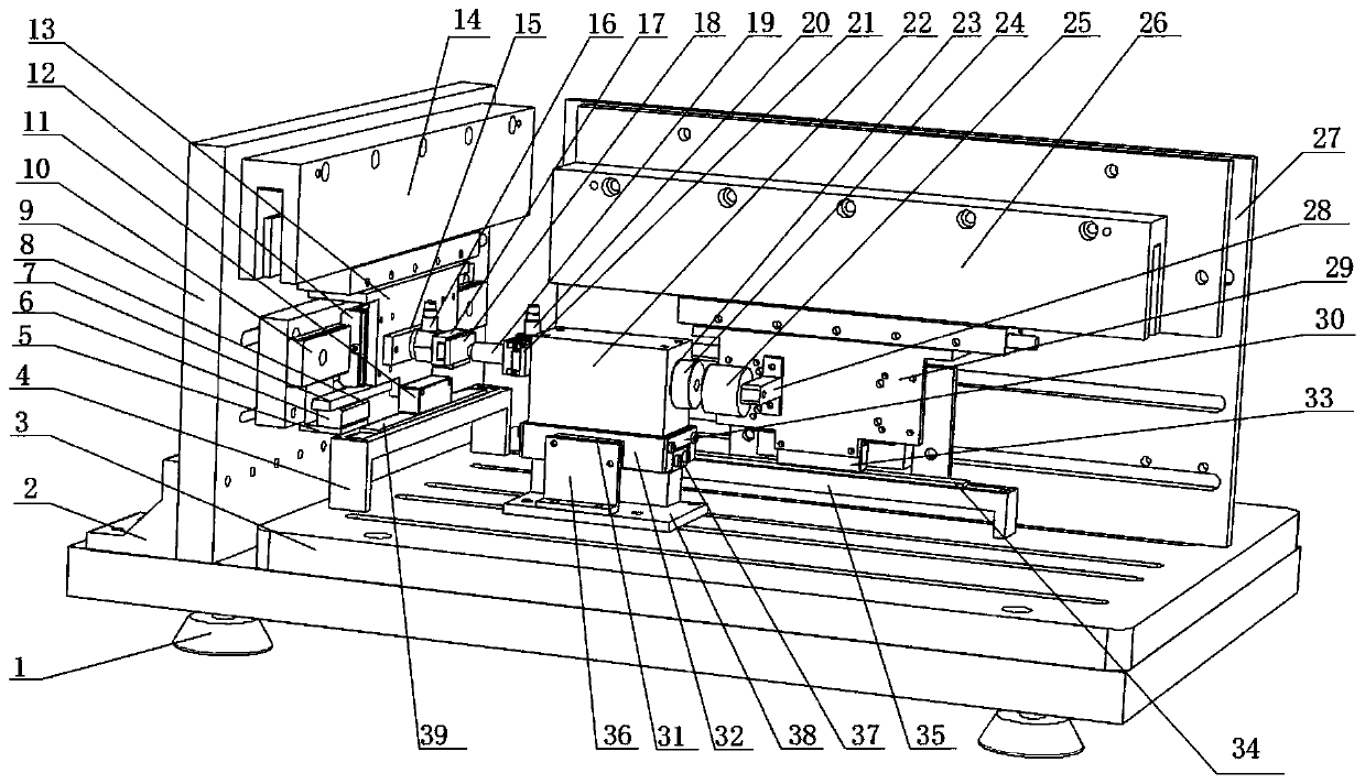
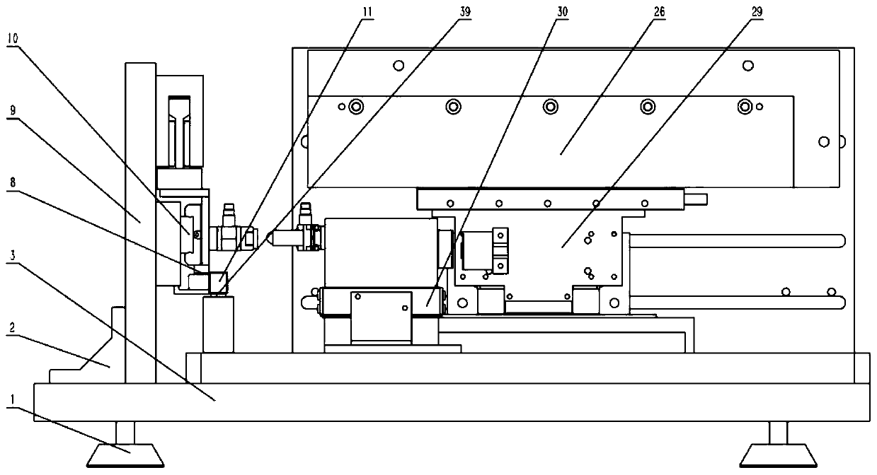
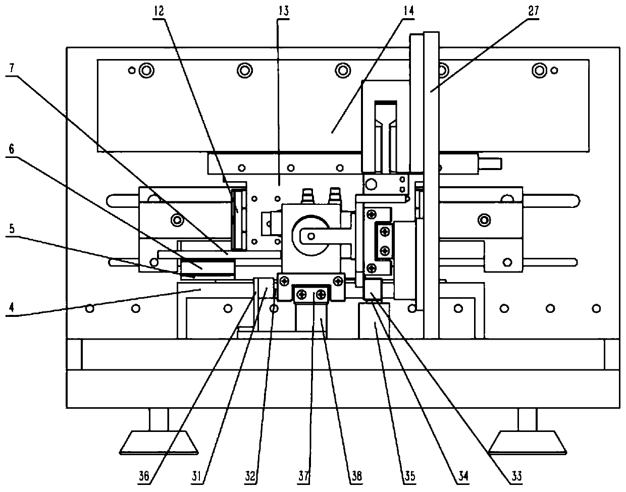
[0035] Such as Figure 1-5 As shown, this embodiment provides a punching wear test device based on control energy, which is divided into mechanical components, control system and data acquisition system, mainly including tangential drive unit, impact unit, and impact drive unit. The tangential drive unit, the impact unit, and the impact drive unit are all provided with a position detection mechanism; the tangential drive unit is used to drive the sample 18 to perform tangential movement; the impact unit is driven by the impact drive unit to perform reciprocating motion, The moving direction of the sample 18 is perpendicular to the moving direction of the impact unit, and the farthest end of the impact head 19 of the impact unit collides with the sample 18 to wear.

[0036] During implementation, also comprise frame, frame comprises base 1, base plate 3, side plate 9 and front plate 27; Described base plate 3 is positioned at base 1 top, and mutually perpendicular between descr...

Embodiment 2

[0050]The difference between this embodiment and Embodiment 1 is that the sample 18 is a tubular sample, and the tubular sample is installed on the pipe clamp 1708 through a splint 1710 and two symmetrical hexagonal bolts 1709; 1708 is fixed on the single-head heating tube fixing plate 1702 by bolts; the single-head heating tube fixing plate 1702 is installed on the impact force sensor through the heat-insulating ceramic plate 1703; the single-head heating tube fixing plate 1702 is installed through clearance fit There are two single-head heating tubes 1704 , and a thermocouple thermometer 1705 is set in the middle of the single-head heating tube fixing plate 1702 ; a heat-insulating ceramic column 1712 is set between the impact unit and the impact head 19 . During implementation, the heat insulating ceramic column 1712 is located between the impact head 19 and the tangential force sensor mounting frame 21; the heat insulating ceramic column / plate is used for heat insulation fr...


PUM


Abstract

The invention discloses a punching abrasion testing device based on control energy, and makes up the deficiencies of multiple existing frictional wear testing devices and research methods. The punching abrasion testing device based on control energy mainly comprises a rack, a tangential linear motor, a test specimen fixture, an impact linear motor, an accurate magnetic grid sensor, an impact block, an electric sucking disk, a silicon steel sheet, a pressure sensor and a grating sensor, wherein the accurate magnetic grid sensor is used for feeding back the motion of the linear motor in real time; the electric sucking disk and the silicon steel sheet are used for controlling the impact block to move; the pressure sensor is used for collecting impact force and tangential force; and the grating sensor is used for collecting the motion of the impact block and the tangential motion of the test specimen. By use of the device, through design that a method of speed and quality control is adopted to control the energy of the impact block, impact and tangential compound abrasion is realized by a punching coupling motion way, and the defect that an existing tester researches a punching abrasion process only from the perspective of force is effectively overcome.

Description

technical field [0001] The invention belongs to experimental devices, in particular to a punching wear test device based on energy control. Background technique [0002] Punching wear is the damage to the material interface caused by repeated dynamic contact and impact between two solid surfaces. Punching wear widely exists in people's life and production, such as: aerospace, rail transit, nuclear power, and other fields. Punching wear will seriously reduce the working efficiency, accuracy and reliability of important parts, and also cause loss of metal materials. The economic loss caused by punching friction and wear every year is immeasurable. Friction and wear will cause different degrees of damage and failure on the surface of materials, and in severe cases, it will lead to failure of mechanical parts. In the form of friction and wear, punching wear is also the most complicated. In order to study this type of wear, so far, different types of testing machines have been ...

Claims


Application Information

Patent Timeline
IPC IPC(8): G01N3/56G01N3/38
CPCG01N3/38G01N3/56G01N2203/001G01N2203/0222G01N2203/0617G01N2203/0641G01N2203/0676G01N2203/0682
Inventor 蔡振兵尹美贵张志星俞延庆林禹朱旻昊周仲荣
Owner SOUTHWEST JIAOTONG UNIV
Why Eureka
Try Eureka