
Resonance-free voltage transformer

A voltage transformer and harmonic-free technology, which is applied in the field of circuit protection devices, can solve the problems of voltage transformer temperature rise, inconvenient control and use, and inability to play a protective role, so as to save space and facilitate monitoring and instruction Effect of adjustment and convenience of internal wiring

Active Publication Date: 2019-07-19
国网新疆电力有限公司公司哈密供电公司 +3
View PDF5 Cites 0 Cited by
  • Summary
  • Abstract
  • Description
  • Claims
  • Application Information

AI Technical Summary

Problems solved by technology

However, the charge and discharge path of the relative ground capacitance of the power grid must pass through the primary winding of the voltage transformer. Once a ground fault occurs in the system, the impedance of the system network to ground tends to be inductive. At this time, if the ground inductance of the system network matches the ground capacitance, it will Forming a three-phase or single-phase resonance circuit can excite various ferromagnetic resonance overvoltages and generate a large inrush current, which will increase the temperature of the voltage transformer or even burn it out, so it is necessary to install a resonance eliminator
However, nowadays the voltage transformer box is too small to install an independent resonance eliminator. Therefore, the voltage transformer needs to be replaced at the same time when installing the resonance eliminator, which is cumbersome to operate and easily causes a lot of waste of resources.
Moreover, the harmonic eliminators currently on the market are not intelligent, and are not convenient enough to control and use, and cannot play a good protective role

Method used


Image

  • Resonance-free voltage transformer
  • Resonance-free voltage transformer
  • Resonance-free voltage transformer

Examples


Embodiment Construction

[0022] The following will clearly and completely describe the technical solutions in the embodiments of the present invention with reference to the accompanying drawings in the embodiments of the present invention. Obviously, the described embodiments are only some, not all, embodiments of the present invention. Based on the embodiments of the present invention, all other embodiments obtained by persons of ordinary skill in the art without making creative efforts belong to the protection scope of the present invention.

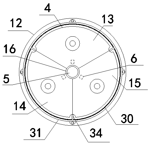
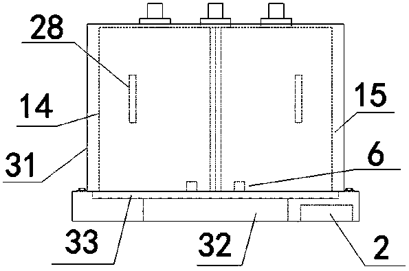
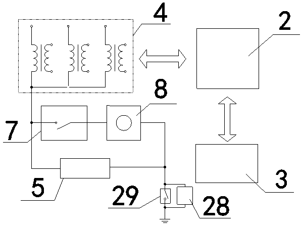
[0023] see Figure 1~5 , a harmonic-free voltage transformer, including a working module 1, a main control unit 2 and an operating device 3, the working module 1 includes a voltage transformer 4 and a resonance eliminator 5; the voltage transformer 4 is cylindrical as a whole structure, the voltage transformer 4 is equally divided into three fan-shaped single-phase voltage transformer units, which are respectively the first unit 13, the second unit 14 and the ...


PUM


Abstract

The invention discloses a resonance-free voltage transformer, which comprises a work module, a main control unit and an operation device, wherein the work module comprises a voltage transformer and aresonance eliminator; a conducting groove is formed in a position of a center axial line of the voltage transformer; the resonance eliminator is inserted and connected inside the conducting groove; one end of the resonance eliminator and the conducting groove are mutually connected in series through current, so that the resonance eliminator and the voltage transformer are combined into a whole; the main control unit comprises a microprocessor, a memory, an information collecting module and a timing module; the information collecting module is in communication connection with the voltage transformer and the microprocessor; and the microprocessor is in communication connection with the memory, the timing module and the operation device. The resonance eliminator is arranged inside the conducting groove in a pluggable and dismountable way; the replacement and the overhaul are convenient; a great space is effectively saved; the intelligentization of a system is effectively improved; the monitoring and the overhaul of equipment are convenient; the work efficiency is improved; and the safety is enhanced.

Description

technical field [0001] The invention relates to the technical field of a circuit protection device, in particular to a harmonic-free voltage transformer. Background technique [0002] Potential transformer is a kind of power equipment widely used in power system. It belongs to a transformer with iron core. It is composed of primary and secondary coils, iron core and insulating layer. However, the charge and discharge path of the relative ground capacitance of the power grid must pass through the primary winding of the voltage transformer. Once a ground fault occurs in the system, the impedance of the system network to ground tends to be inductive. At this time, if the ground inductance of the system network matches the ground capacitance, it will The formation of a three-phase or single-phase resonant circuit can excite various ferromagnetic resonance overvoltages and generate a large inrush current, which will increase the temperature of the voltage transformer or even burn...

Claims


Application Information

Patent Timeline
Patent Type & Authority Applications(China)
IPC IPC(8): G01R15/18G01K1/02
CPCG01R15/18G01K1/02
Inventor 张泽强夏永平朱文彬赵普志薛劲莹王明颜晓东程飞张建忠李明郑义贾言争吴伟丽刘勇刘俊
Owner 国网新疆电力有限公司公司哈密供电公司
Learn More