High-strength magnetic-gathering permanent-magnet rotor and motor

A permanent magnet rotor, high-strength technology, applied in the direction of magnetic circuit rotating parts, magnetic circuits, electrical components, etc., to achieve the effect of high rotor strength, reducing eddy current loss, and improving magnetic concentration ability

Inactive Publication Date: 2019-07-19
NANJING UNIV OF AERONAUTICS & ASTRONAUTICS
View PDF6 Cites 3 Cited by
  • Summary
  • Abstract
  • Description
  • Claims
  • Application Information

AI Technical Summary

Problems solved by technology

[0004] The purpose of the present invention is to provide a high-strength magnetism-concentrating permanent ma

Method used


Image

  • High-strength magnetic-gathering permanent-magnet rotor and motor
  • High-strength magnetic-gathering permanent-magnet rotor and motor
  • High-strength magnetic-gathering permanent-magnet rotor and motor

Examples


Embodiment 1

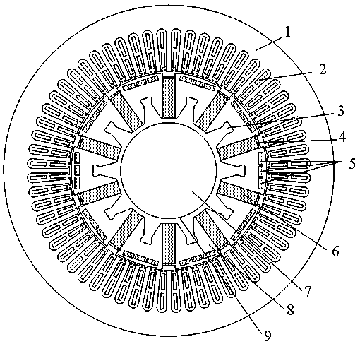
[0033] The high-strength magnetism-concentrating permanent magnet rotor of the present invention includes a rotor iron core and a permanent magnet. A number of permanent magnet slots are evenly opened on the rotor iron core along its circumferential direction, and the permanent magnet slots are arranged through the direction of the rotating shaft. There are suitable tangential permanent magnets, and there is a slot on the rotor iron core along its circumference. The slot is arranged through the direction of the rotating shaft. At least two in-line slots and two in-line permanent magnets are arranged between the two permanent magnet slots. The permanent magnet slots and the tangential permanent magnets are arranged in pairs in even groups, generally 6-12 even groups.

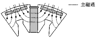
[0034] The cross-section of the tangential permanent magnet is a rectangle, and the tangential magnetization method is adopted. A magnetic steel baffle is installed on the end face of the tangential permanent ma...

Embodiment 2

[0036] In the high-strength magnet-concentrating permanent magnet rotor of the present invention, at least N inline slots and N inline permanent magnets are arranged between two adjacent permanent magnet slots, and N satisfies the following relationship: 4≥N≥2. Assuming that the gap between adjacent inline permanent magnets 5 is A, then A satisfies the following relationship: 3mm≥A≥1mm. Assuming that the section length of each inline permanent magnet 5 is B and the width is C, then B, C and N satisfy the following relationship: 6≥(N*(A+B)-A) / C≥4. Among them, the total mechanical angle occupied by the N inline permanent magnets 5 with the center of the rotor circle and the total length of the gap is α, and the mechanical angle occupied by the rotor core part of each module is β, and α and β satisfy the following relationship: 0.9≥α / β≥0.5. The shortest distance between the inline permanent magnets 5 on both sides, that is, the inline permanent magnets 5 close to the tangential ...

Embodiment 3

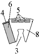
[0039] Optionally, in this example, an annular groove is left between the rotor core 8 and the rotating shaft 7, and the annular groove 9 protrudes toward the air gap side to provide a dovetail groove 3, and the dovetail groove 3 is evenly spaced between two adjacent permanent magnets. Between the grooves, the annular groove 9 and the dovetail groove 3 are embedded with lightweight high-strength alloy materials for enhancing the strength of the rotor. High-strength titanium alloy material is embedded in the groove, and an integral reinforced structure is adopted. The density of high-strength titanium alloy is only 60% of that of steel, and its strength is higher than that of iron core material.


PUM


Abstract

The invention provides a high-strength magnetic-gathering permanent-magnet rotor according to the problem of limitation of overload capacity and rotor strength of an existing built-in tangential permanent-magnet motor. The high-strength magnetic-gathering permanent-magnet rotor comprises a rotor core and a permanent magnet, wherein a plurality of permanent-magnet grooves are uniformly formed in the rotor core along a circumferential direction, the permanent-magnet grooves are arranged along a direction of a rotation shaft in a penetrating way, adaptive tangential permanent magnets are arrangedin the permanent-magnet grooves, linear grooves are formed in the rotor core at intervals along a circumferential direction, the linear grooves are arranged along the direction of the rotation shaftin a penetrating way, linear permanent magnets are arranged in the linear grooves, at least two linear grooves arranged in a straight line way and two of the linear permanent magnets are arranged between two adjacent permanent-magnet grooves. A light and high-strength alloy material is embedded to an inner side of the rotor core, the rotor weight is reduced, and the rotor strength is improved. Thehigh-strength magnetic-gathering permanent-magnet motor has the characteristics of high overload capability, high rotor strength, high power density, high modular degree and the like and is suitablefor application occasions such as an aviation permanent-magnet starting power generation system.

Description

technical field [0001] The invention relates to the field of motor design, in particular to a high-strength magnetism-concentrating permanent magnet rotor and a motor, which are suitable for application occasions such as aviation permanent magnet starting and generating systems. Background technique [0002] As an aviation starter / generator or a high power density drive motor, the permanent magnet motor must not only meet the torque requirements in the low speed area, but also provide sufficient output power stably in the high speed area. At the same time, the motor must also meet the requirements of high power density, high reliability requirements. Therefore, the design process is more complicated than ordinary motors, and it needs to meet the requirements of high strength, strong overload capacity and light weight. [0003] Based on the requirement of high rotor strength for permanent magnet motors, permanent magnet segments and dovetail slots need to be applied to the r...

Claims


Application Information

Patent Timeline
IPC IPC(8): H02K1/27
CPCH02K1/274
Inventor 张卓然高华敏刘业王晨姜文颖
Owner NANJING UNIV OF AERONAUTICS & ASTRONAUTICS
Why Eureka
Try Eureka