
Microgravity vacuum environment oriented lunar surface in-situ resource 3D printing device

A 3D printing, vacuum environment technology, applied in the directions of manufacturing auxiliary devices, 3D object support structures, accessories for processing main materials, etc., can solve the problems of long construction period, waste of transportation resources, and difficulty in meeting, to expand production scale, reduce Manufacturing cost and effect of improving production efficiency

Active Publication Date: 2019-07-23
HUAZHONG UNIV OF SCI & TECH
View PDF3 Cites 14 Cited by
  • Summary
  • Abstract
  • Description
  • Claims
  • Application Information

AI Technical Summary

Problems solved by technology

But there are more difficulties in establishing a base on the moon
The reasons are as follows: First, if the production materials are transported from the earth to the surface of the moon, multiple launches of heavy-duty launch vehicles are required, which is not only costly, but also takes a long time to build. Extreme demand for unmanned intelligent production
[0004] In addition, today's production of mechanical parts and frame structures requires a large number of equipment such as milling equipment, welding equipment, and construction elevators, as well as skilled workers. These conditions are difficult to meet in the manufacture of lunar structures
However, the existing 3D printing devices in outer space, such as "3D printing implementation method, printing unit and spinneret flow control method in space environment" (public number: CN105172134A), are all externally carried materials to space for 3D printing. Carrying materials into space itself wastes a lot of transportation resources, which is not conducive to the construction of outer space bases such as the moon

Method used


Image

  • Microgravity vacuum environment oriented lunar surface in-situ resource 3D printing device
  • Microgravity vacuum environment oriented lunar surface in-situ resource 3D printing device
  • Microgravity vacuum environment oriented lunar surface in-situ resource 3D printing device

Examples


Embodiment Construction

[0032] In order to make the object, technical solution and advantages of the present invention clearer, the present invention will be further described in detail below in conjunction with the accompanying drawings and embodiments. It should be understood that the specific embodiments described here are only used to explain the present invention, not to limit the present invention. In addition, the technical features involved in the various embodiments of the present invention described below can be combined with each other as long as they do not constitute a conflict with each other.

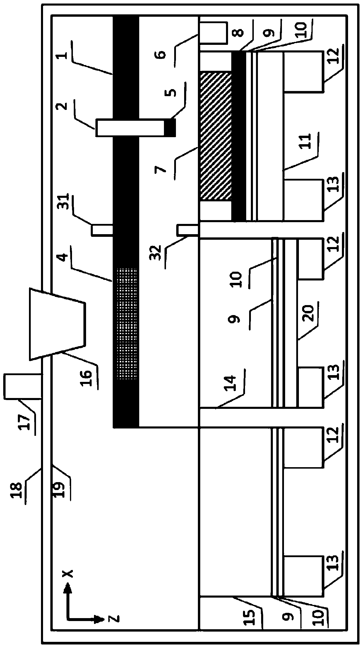
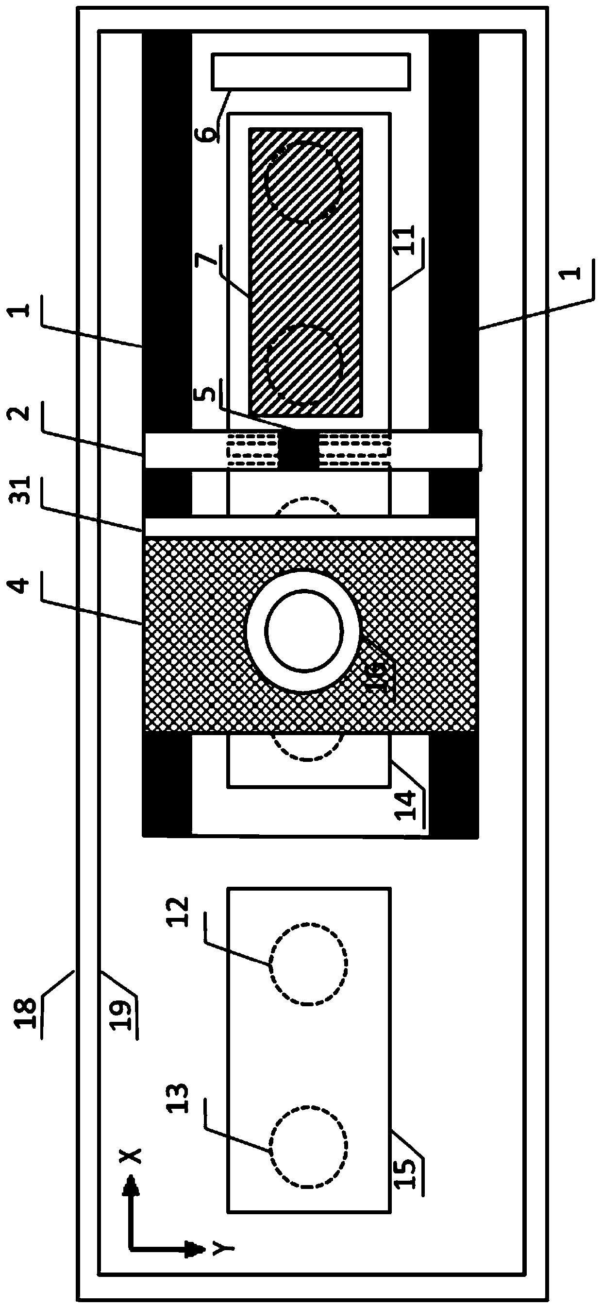
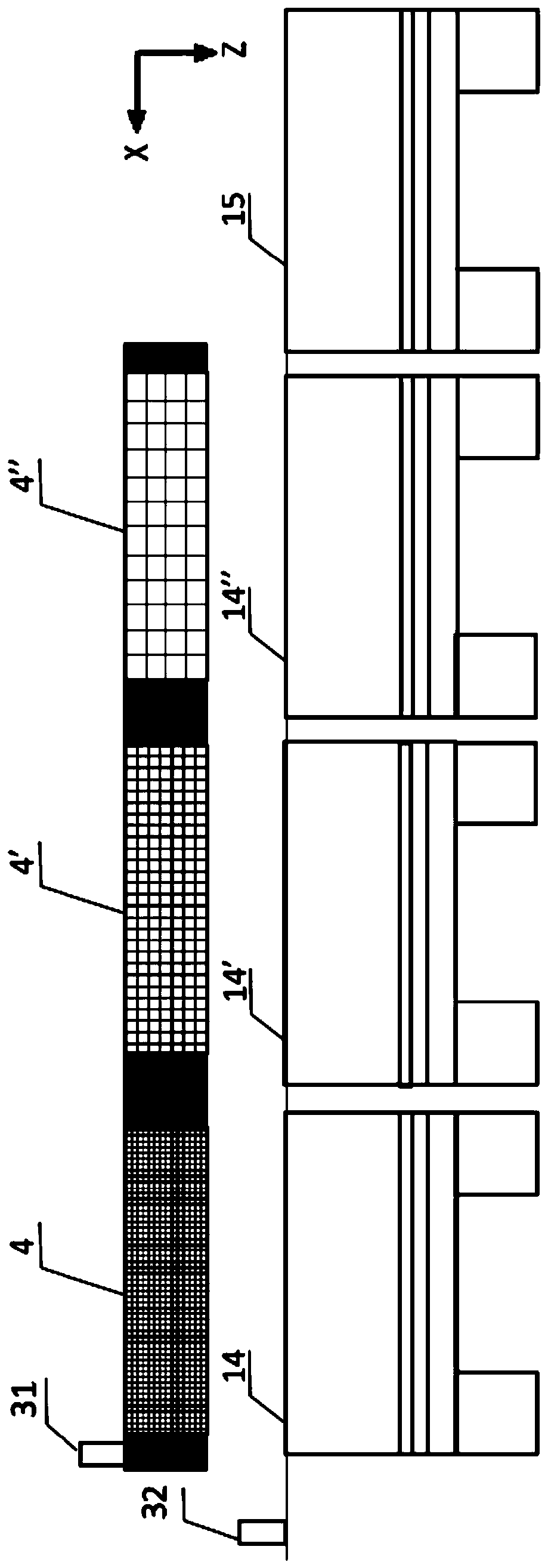
[0033]The present invention provides a 3D printing device for in-situ resources on the lunar surface facing a microgravity vacuum environment, mainly including a grasping and screening unit for in-situ resources on the lunar surface, and an inkjet 3D printing forming unit. The existing 3D printing devices in outer space all carry materials to outer space for 3D printing. Carrying materials waste...


PUM


Abstract

The invention discloses a microgravity vacuum environment oriented lunar surface in-situ resource 3D printing device, and belongs to the manufacturing field of spatial additive manufacturing. The device is characterized in that the obtaining and screening of surface particular materials of lunar soil, lunar dust and the like are achieved by a lunar surface in-situ resource grabbing and screening unit; a 3D printing shaping unit is formed through ink jetting, 3D printing is conducted by using screened particular materials, and the device is suitable for lunar surface microgravity vacuum environment and the 3D printing manufacturing of large components of future lunar base. The device has the advantages that the lunar surface in-situ resources are taken as printing consuming materials, the materials do not need to be carried to the moon through spatial transportation, so that transportation energy consumption is greatly reduced, the manufacturing cost is reduced, and the device is particularly suitable for the production of components of lunar base building facilities, mechanical parts and the like.

Description

technical field [0001] The invention belongs to the field of space additive manufacturing, and more specifically relates to a 3D printing device for in-situ resources on the lunar surface facing a microgravity vacuum environment. Background technique [0002] 3DP (Three Dimensional Printing and Gluing), three-dimensional printing bonded forming, inkjet deposition, also known as binder jetting (Binder Jetting), inkjet powder printing (Inkjet Powder Printing). This process belongs to the category of "liquid jet printing and forming". The process is similar to traditional 2D inkjet printers, and it is one of the forming technologies that best fit the concept of "3D printing". It was first developed by the Massachusetts Institute of Technology (MIT) in 1993. The basic principle of this technology is to use the nozzle to spray the binder to selectively bond the powder to form three-dimensional parts. The process flow is as follows: (1) first slice the 3D CAD model of the pre-p...

Claims


Application Information

Patent Timeline
IPC IPC(8): B29C64/165B29C64/20B29C64/307B29C64/25B29C64/255B33Y30/00B33Y40/00
CPCB29C64/165B29C64/20B29C64/25B29C64/255B29C64/307B33Y30/00B33Y40/00
Inventor 宋波张磊史玉升
Owner HUAZHONG UNIV OF SCI & TECH
Learn More