
Air compression device and air compressor

An air compression and cylinder technology, applied in mechanical equipment, machines/engines, liquid variable capacity machinery, etc., can solve the problems of complex structure of air compression devices, limited working time, poor cooling performance, etc., to improve continuous work. Time and working life, lower working temperature, effect of simple structure

Pending Publication Date: 2019-07-23
浙江万安其弗汽车零部件有限公司
View PDF10 Cites 2 Cited by
  • Summary
  • Abstract
  • Description
  • Claims
  • Application Information

AI Technical Summary

Problems solved by technology

[0005] The technical problem to be solved by the present invention is to solve the technical defects of the air compression device in the prior art, such as complex structure, high cost, limited working time and limited working life due to poor cooling performance

Method used


Image

  • Air compression device and air compressor
  • Air compression device and air compressor
  • Air compression device and air compressor

Examples


Embodiment Construction

[0042] In order to make the object, technical solution and advantages of the present invention clearer, the present invention will be further described in detail below in conjunction with the accompanying drawings and embodiments. It should be understood that the specific embodiments described here are only used to explain the present invention, not to limit the present invention.

[0043] In the description of the present invention, it should be understood that the orientation or positional relationship indicated by the terms "upper", "lower", "front", "rear", "inner", "outer" etc. Orientation or positional relationship is only for the convenience of describing the present invention and simplifying the description, and does not indicate or imply that the referred device or element must have a specific orientation, be constructed and operated in a specific orientation, and thus should not be construed as a limitation of the present invention.

[0044] In the description of the...


PUM


Abstract

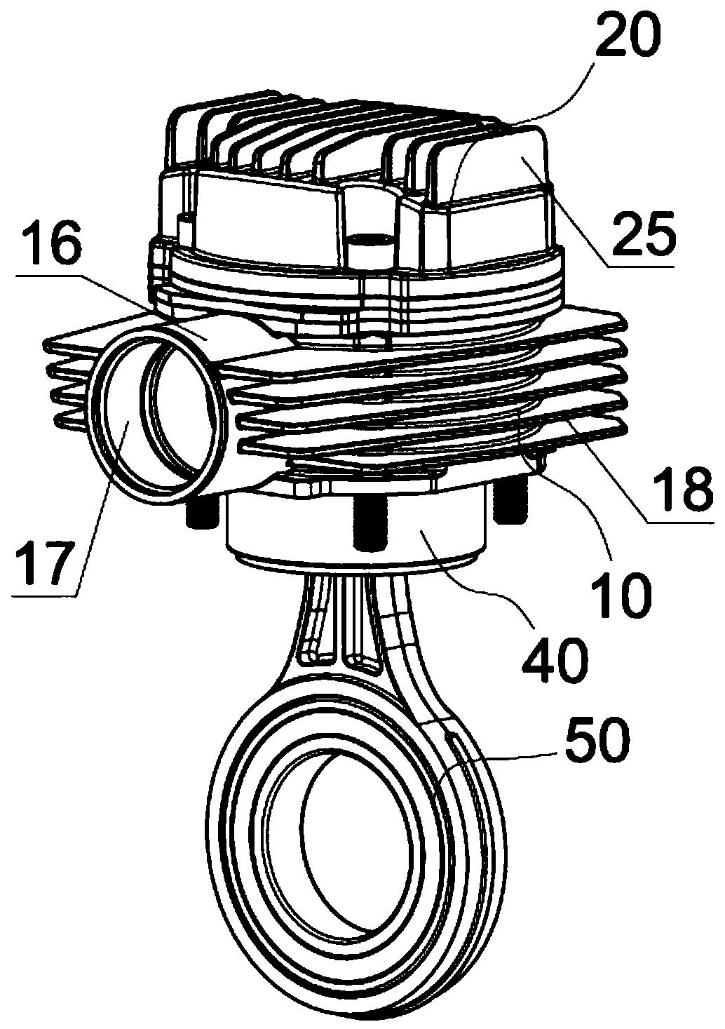
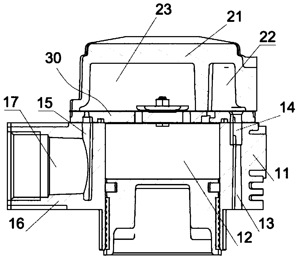
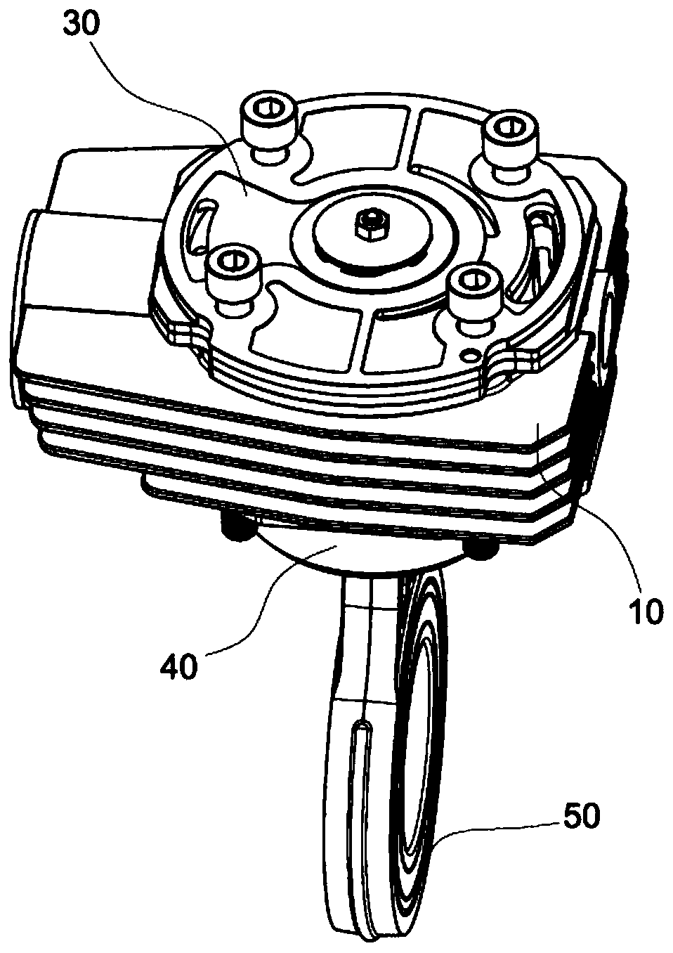
The invention relates to the technical field of air compression, in particular to an air compression device and an air compressor. The air compression device comprises an air cylinder, an air cylinderhead, a piston assembly, a connecting rod and a valve plate assembly. The air cylinder comprises an air cylinder body and a piston cavity axially penetrating through the air cylinder body. The pistonassembly is slidably connected with the piston cavity in a sealed mode. The valve plate assembly is fixedly connected between the air cylinder head and the air cylinder. According to the air compression device of the structure, the valve plate assembly has the functions of air suction and exhausting, compared with the mode that an air suction component and an exhaust component are separately arranged in the prior art, the structure is simpler and more compact, and the production cost is lower, the assembly efficiency is higher, and due to the integrated functions, replacement and repair are more convenient. The air cylinder and the air cylinder head have a cooling and heat dissipation mode combining internal cooling and external heat dissipation, the working temperature can be effectivelylowered, and thus the continuous working time and service life of the air compression device are prolonged.

Description

technical field [0001] The invention relates to the technical field of air compression, in particular to an air compression device and an air compressor. Background technique [0002] The electric air compressor is the main body of the air source device. It is a device that converts the mechanical energy of the prime mover (usually a motor) into gas pressure energy. It is a pressure generating device for compressing air. The core structure of the electric air compressor is air. compression device. [0003] The air compression device in the prior art usually includes a cylinder, a cylinder head, a piston and a connecting rod mechanism connected with the piston, wherein the cylinder has a piston chamber inside, and the piston reciprocates in the piston chamber. Wherein the cylinder head is generally provided with an exhaust port, an exhaust assembly is provided between the cylinder head and the cylinder, and an air intake assembly is provided at the top of the piston. Its wo...

Claims


Application Information

Patent Timeline
Patent Type & Authority Applications(China)
IPC IPC(8): F04B39/12F04B39/06F04B39/10
CPCF04B39/122F04B39/06F04B39/125F04B39/1046
Inventor 肖东明姚灿均王玉亮
Owner 浙江万安其弗汽车零部件有限公司
Learn More