Sample manufacturing method for representing blade body performance of thin-walled blade casting

A manufacturing method and thin-walled technology, which are applied in the preparation of test samples, sampling devices, etc., can solve the problem of inability to accurately characterize the tissue characteristics of thin-walled leaves.

Active Publication Date: 2019-07-23
AECC COMML AIRCRAFT ENGINE CO LTD
View PDF6 Cites 5 Cited by
  • Summary
  • Abstract
  • Description
  • Claims
  • Application Information

AI Technical Summary

Problems solved by technology

With the improvement of the blade, the wall thickness of the blade body gradually decreases (1mm and below), and usually the standard large sample obtained by single casting cannot accurately characterize the microstructure of the thin-walled blade.

Method used


Image

  • Sample manufacturing method for representing blade body performance of thin-walled blade casting
  • Sample manufacturing method for representing blade body performance of thin-walled blade casting
  • Sample manufacturing method for representing blade body performance of thin-walled blade casting

Examples


Embodiment 1

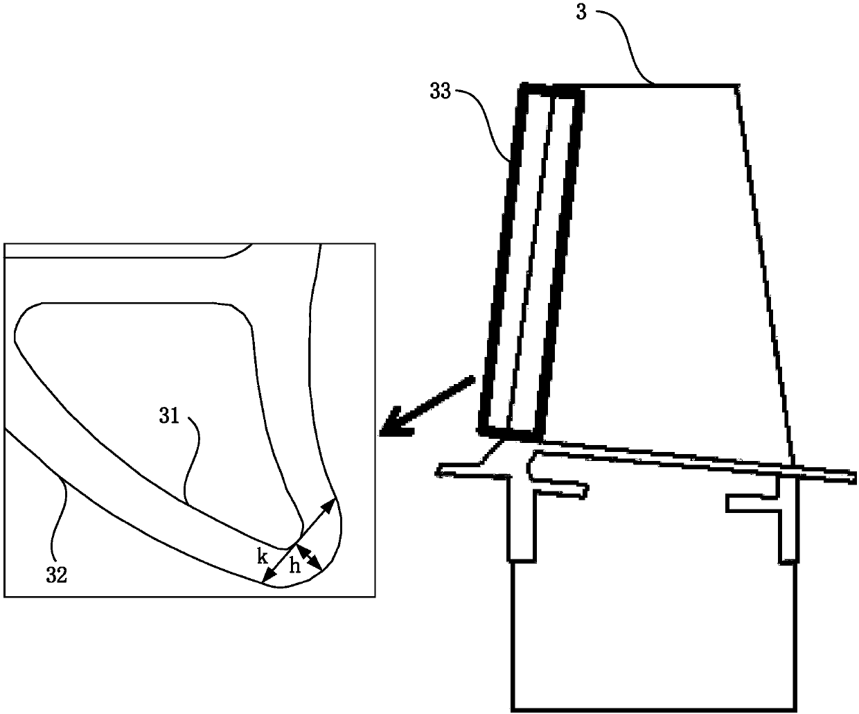
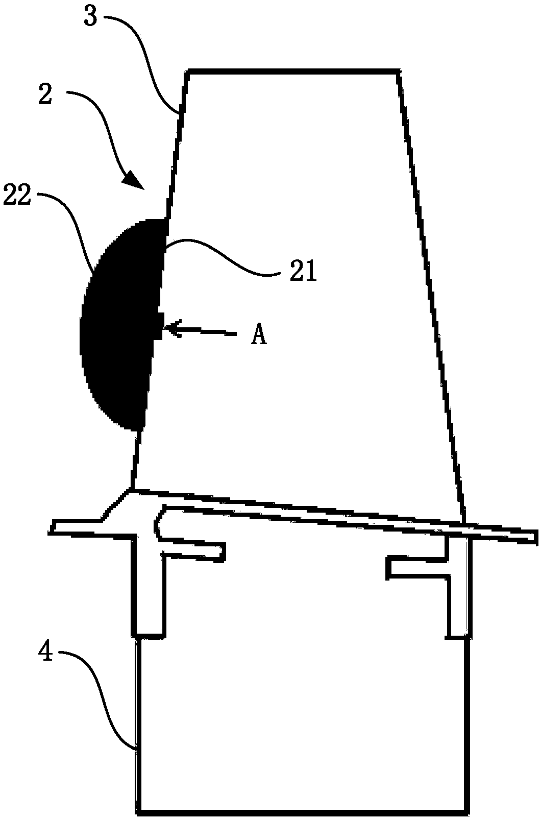
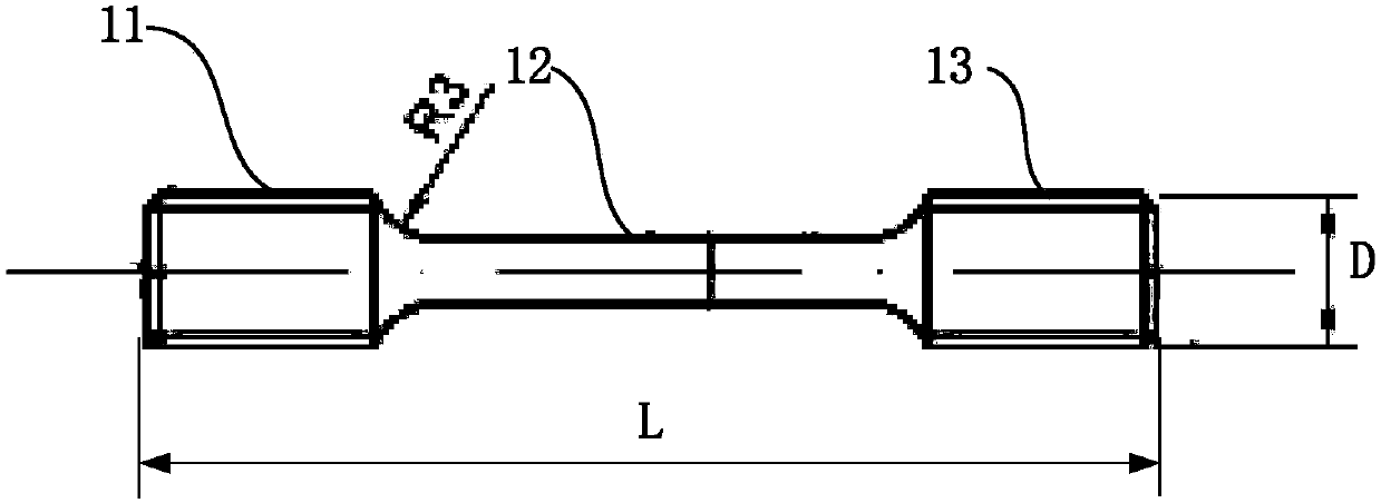
[0066] Embodiment 1: Take thin-walled blades as moving blades as an example. First, select the part that needs to be sampled from the airfoil (single crystal nickel-based superalloy turbine working blade), and then designate the position of the air inlet edge 80mm from the bottom of the tenon as the performance test point (such as Figure 4 ), the test location is usually selected comprehensively considering the temperature and stress of the working condition. According to the largest diameter of test specimen 1 (eg image 3 diameter of 6mm), length (such as image 3 40mm), and the wall thickness h of the intake side (such as figure 1 1mm), thicken the inlet edge of the thin-walled blade with the selected test point A as the center. The principles of thickening are as follows:

[0067] 1. The outer surface 32 is thickened, and the inner surface 31 remains unchanged;

[0068] 2. The position of the thickened edge should be smoothly transitioned, Figure 4 R1 and R2 should...

Embodiment 2

[0072] Embodiment 2: firstly select the part (equiaxed nickel-based superalloy turbine working blade) that needs to be sampled from the airfoil, and then designate the position of the inlet edge at the 80mm distance from the tenon bottom as the performance test point (such as Figure 4 ), the test location is usually selected comprehensively considering the temperature and stress of the working condition. According to the maximum diameter of the test specimen (1) (eg image 3 The diameter of 6mm), length (such as image 3 40mm), and the wall thickness h of the intake side (such as figure 1 1mm), and the position of the inlet edge of the blade is thickened with the selected test point as the center. The principles of thickening are as follows:

[0073] 1. The outer surface 32 is thickened, and the inner surface 31 remains unchanged;

[0074] 2. The position of the thickened edge should be smoothly transitioned, Figure 4 R1 and R2 should be controlled within R0.5-R3.0.

...


PUM

PropertyMeasurementUnit
thicknessaaaaaaaaaa
radiusaaaaaaaaaa
diameteraaaaaaaaaa

Abstract

The invention discloses a sample manufacturing method for representing the blade body performance of a thin-walled blade casting, which relates to the field of thin-walled blade testing, and is used for accurately and conveniently extracting a sample capable of representing the blade body performance of a thin-walled blade. The sample manufacturing method comprises the following steps: manufacturing a thin-walled blade including a thickened part, wherein the thickness of the thickened part is greater than the thickness of other parts of the thin-walled blade body; sampling from the thickened part; and processing the taken sample into a sample of a set shape. In the technical scheme, the thin-walled blade including the thickened part are manufactured before sampling the thin-walled blade; and the tissue morphology of the thickened part is the same or nearly the same as the tissue morphology of other parts of the thin-walled blade body. Then samples are taken from the thickened part andthen processed to the desired shape. The above technical scheme realizes sampling of the thin-walled blade, and the sample performance represents the performance of the blade body.

Description

technical field [0001] The invention relates to the field of thin-walled blade testing, in particular to a sample manufacturing method for characterizing performance of thin-walled blade castings. Background technique [0002] Nickel-based superalloys are used in working blades (rotor blades) and guide blades of gas turbines and aeroengines. Their service life is mainly limited by fatigue, creep and hot corrosion at elevated service temperatures. An effective solution to increase lifetime is to reduce material temperature by cooling. In order to optimize the cooling efficiency and reduce the weight of the turbine rotor blades, the method of reducing the wall thickness of the blade castings is generally adopted. The successful design of advanced blades requires reasonable creep-rupture life predictions based on size effects. [0003] The inventors found that there are at least the following problems in the prior art: conventional performance tests usually use standard larg...

Claims


Application Information

Patent Timeline
Patent Type & Authority Applications(China)
IPC IPC(8): G01N1/28G01N1/08
CPCG01N1/28G01N1/08
Inventor 朱鸥李玉龙常建卫张燕
Owner AECC COMML AIRCRAFT ENGINE CO LTD
Why Eureka
Try Eureka