Light source regulation method for LCD glass substrate defect detection

A technology for glass substrate and defect detection, applied in measuring devices, material analysis through optical means, instruments, etc., can solve problems such as inability to maintain, achieve high repeatability, and simple and efficient light source adjustment methods

Active Publication Date: 2019-07-23
HEFEI UNIV OF TECH
4 Cites 0 Cited by

AI-Extracted Technical Summary

Problems solved by technology

[0003] Based on the technical problems existing in the background technology, the present invention proposes a light source adjustment method for liquid crystal screen glass substrate defect detection. Two pieces of white paper are used to determine the reference plane where the illuminated area is located and the reference line perpendicular to the moving direction, so that the reflection The reflected illumination area of ​​the light sou...

Method used

In accompanying drawing 4, choose a piece of transparent flat glass, glass width should be greater than detection object width, and glass thickness should be less than 2mm to reduce error. The plane G where the flat glass is located can be regarded as the motion platform detection reference plane T. Paste A4 printing paper S1 and S2 on...

Abstract

The invention discloses a light source regulation method for LCD glass substrate defect detection. Two white papers are used for determining a reference plane where a lighting area is and a datum lineperpendicular to a motion direction, a reflected lighting area of a reflected light source and transmission light area of a transmission light source are overlapped at the datum line and parallel tothe datum line, and perpendicular to a motion direction of a motion platform. The light source regulation method provided by the invention simple and efficient, has high repeatability, is beneficial for operation of experimenters, is beneficial for regulating a light source in practical application, and can be generalized in light source regulation of all robot vision system.

Application Domain

Material analysis by optical means

Technology Topic

Light sourceMotion direction +6

Image

  • Light source regulation method for LCD glass substrate defect detection
  • Light source regulation method for LCD glass substrate defect detection
  • Light source regulation method for LCD glass substrate defect detection

Examples

  • Experimental program(1)

Example Embodiment

[0014] The technical solutions in the embodiments of the present invention will be clearly and completely described below in conjunction with the accompanying drawings in the embodiments of the present invention. Obviously, the described embodiments are only a part of the embodiments of the present invention, rather than all the embodiments.
[0015] Examples.
[0016] A light source adjustment method for defect detection of LCD glass substrates, the design process is as follows:
[0017] (1) The light source model of the LCD glass substrate defect detection system
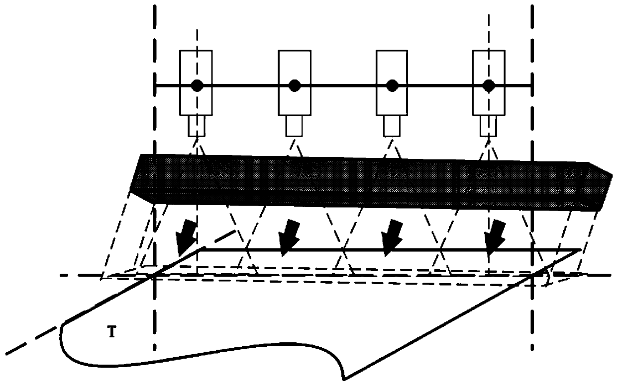
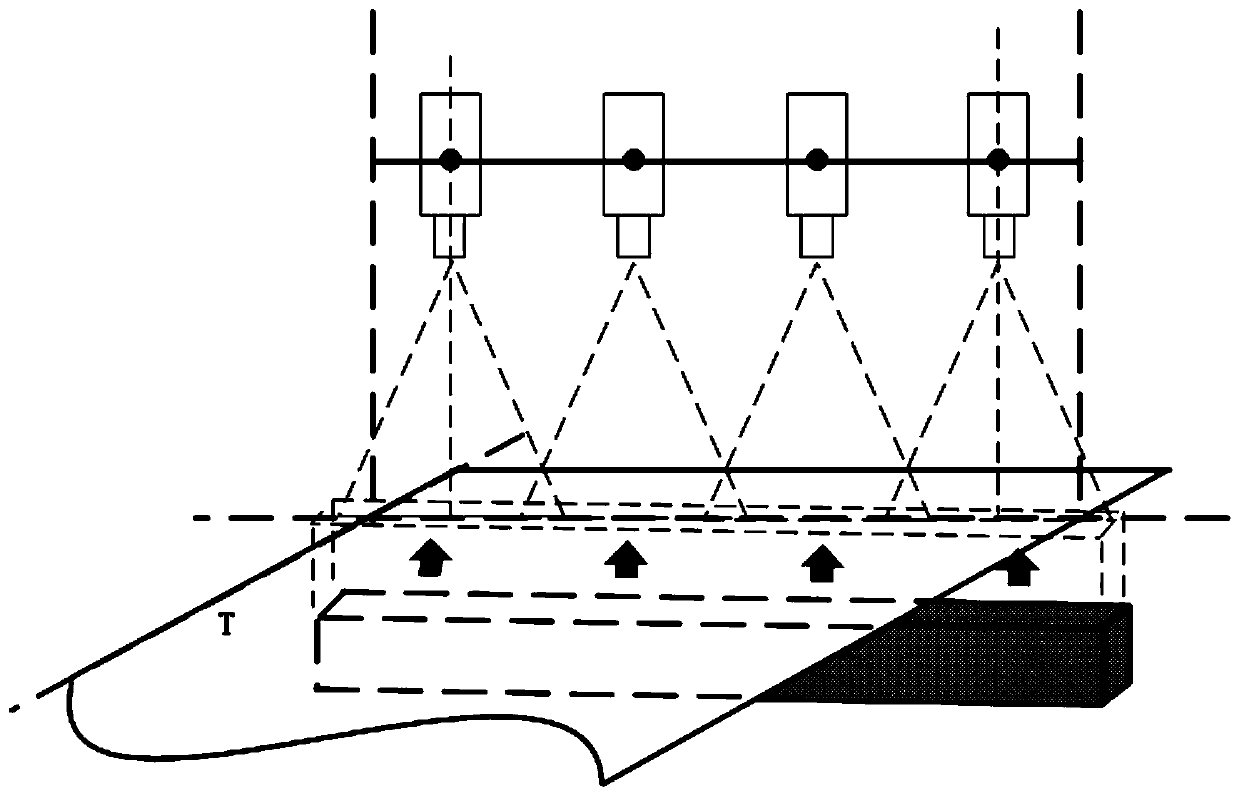
[0018] The light source model for TFT-LCD liquid crystal screen glass substrate defect detection is shown in the figure.
[0019] Attached figure 1 , 2 Shown in is the light source lighting model for traditional LCD glass substrate defect detection. When installing the light source in the imaging system, we can only estimate the approximate position of the light source during routine operation, but cannot accurately calibrate it. When using a strip light source, the effective area with high brightness and uniform brightness in the illuminated area is similar to a long and narrow strip rectangle. If it is not adjusted, the illuminated areas of the initial reflected light source and the transmitted light source are generally prone to cross or dislocation. As attached image 3 Shown. This will cause uneven distribution of the brightness of the image collected by the camera, affect the imaging quality, and reduce the detection accuracy and accuracy of the system.
[0020] In summary, the main problem of light source adjustment for TFT-LCD liquid crystal glass substrate defect detection is to determine the reference plane where the illumination area is located and the reference line perpendicular to the direction of movement, so that the reflected light area of ​​the reflected light source and the transmitted light area of ​​the transmitted light source Overlap at the reference line and parallel to the reference line, perpendicular to the direction of movement of the moving platform.
[0021] (2) Design of light source adjustment method for liquid crystal screen glass substrate defect detection system
[0022] To adjust the illumination area, first determine the reference plane where the illumination area is and the reference line with the illumination position.
[0023] Attached Figure 4 Choose a piece of transparent flat glass, the width of the glass should be greater than the width of the test object, and the thickness of the glass should be less than 2mm to reduce errors. The plane G where the flat glass is located can be regarded as the reference plane T for the motion platform detection. Paste A4 printing paper S on both ends of the glass plane 1 , S 2 , Draw a straight line on the white paper parallel to the glass placement direction l 1 , L 2. When the glass is mounted on the moving platform, when its placement direction is perpendicular to the moving direction, the straight line L where the two line segments are located can be used as the reference line.
[0024] After placing the reference plate glass, start to adjust the reflected light source to l 1 , L 2 As a reference, adjust the position of the reflected light source until l 1 , L 2 Respectively in the light A on the paper S 1 , S 2 The center of the upper illuminated area. Afterwards, the position of the transmitted light source can be adjusted in the same way. After the adjustment is completed, it can be considered that the reflected light area and the transmitted light area overlap the reference line, and are parallel to the reference line and perpendicular to the direction of movement of the moving platform. At this time, the light source has been adjusted to the best Location, the camera can obtain high-quality and stable images.
[0025] The above are only preferred specific embodiments of the present invention, but the protection scope of the present invention is not limited to this. Anyone familiar with the technical field within the technical scope disclosed by the present invention, according to the technical solution of the present invention Equivalent replacements or changes to its inventive concept should all fall within the protection scope of the present invention.

PUM

PropertyMeasurementUnit
Thickness<= 2.0mm

Description & Claims & Application Information

We can also present the details of the Description, Claims and Application information to help users get a comprehensive understanding of the technical details of the patent, such as background art, summary of invention, brief description of drawings, description of embodiments, and other original content. On the other hand, users can also determine the specific scope of protection of the technology through the list of claims; as well as understand the changes in the life cycle of the technology with the presentation of the patent timeline. Login to view more.

Similar technology patents

Preparation method of polymer film with periodic nano-structure and template used by same

InactiveCN101870772Ahigh repeatabilitylow cost
Owner:SHANGHAI INST OF APPLIED PHYSICS - CHINESE ACAD OF SCI

Silurus asotus DNA barcoding standard detection sequence and application thereof

InactiveCN107058603Ashorten identification timehigh repeatability
Owner:ZHENJIANG HUADA DETECTION CO LTD

Microwave shielding clothes shielding efficiency testing system

PendingCN106940405AAvoid the effects of standing waves and harmonicshigh repeatability
Owner:NORTH CHINA ELECTRIC POWER UNIV (BAODING)

Classification and recommendation of technical efficacy words

  • high repeatability

Pulse wind tunnel operation control system and pulse wind tunnel operation control method

ActiveCN106840582AEnsure the safety of personnel operationHigh repeatability
Owner:CHINA ACAD OF AEROSPACE AERODYNAMICS

Mirror angle transducer and mirror tilting mechanism

InactiveUS20050225886A1stable contacthigh repeatability
Owner:MURAKAMI CORP

Piezoelectric balance calibration loading sleeve

ActiveCN106053009Afor quick replacementhigh repeatability
Owner:中国空气动力研究与发展中心超高速空气动力研究所
Why Eureka
Try Eureka