An electrothermal micro-drive control optical circuit on-off device based on u+v structure

A technology of micro-drive and control of light, applied in optics, optical components, instruments, etc., to achieve the effect of good system compatibility, accurate positioning, and effective on-off control

Active Publication Date: 2021-09-03
徐州冀华机电科技有限公司
View PDF8 Cites 0 Cited by
  • Summary
  • Abstract
  • Description
  • Claims
  • Application Information

AI Technical Summary

Problems solved by technology

There is still a research gap in the application of electrothermal micro-drivers to control the on-off of high-energy optical fibers and the realization of MOEMS optical logic control

Method used


Image

  • An electrothermal micro-drive control optical circuit on-off device based on u+v structure
  • An electrothermal micro-drive control optical circuit on-off device based on u+v structure
  • An electrothermal micro-drive control optical circuit on-off device based on u+v structure

Examples


Embodiment 1

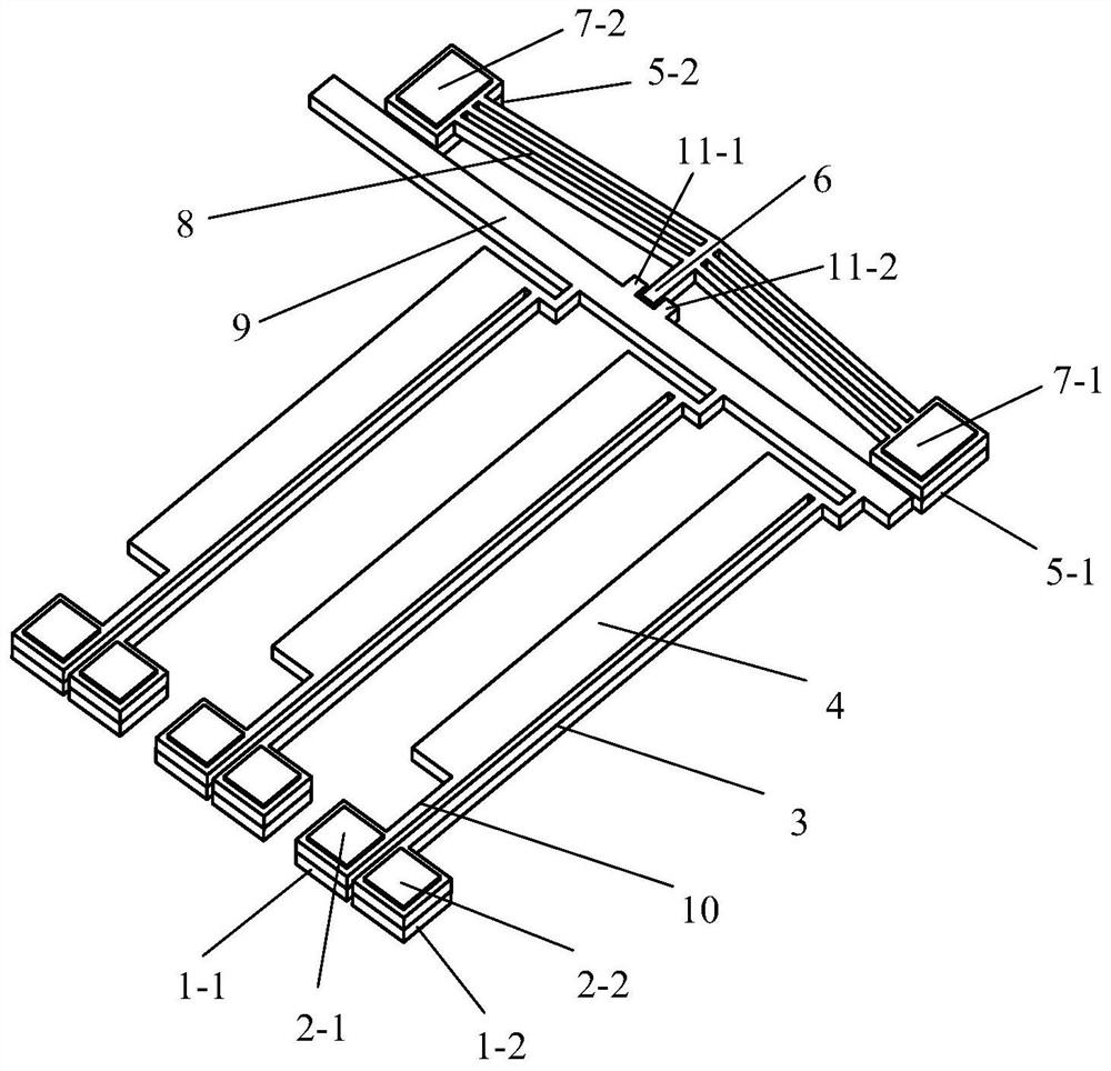
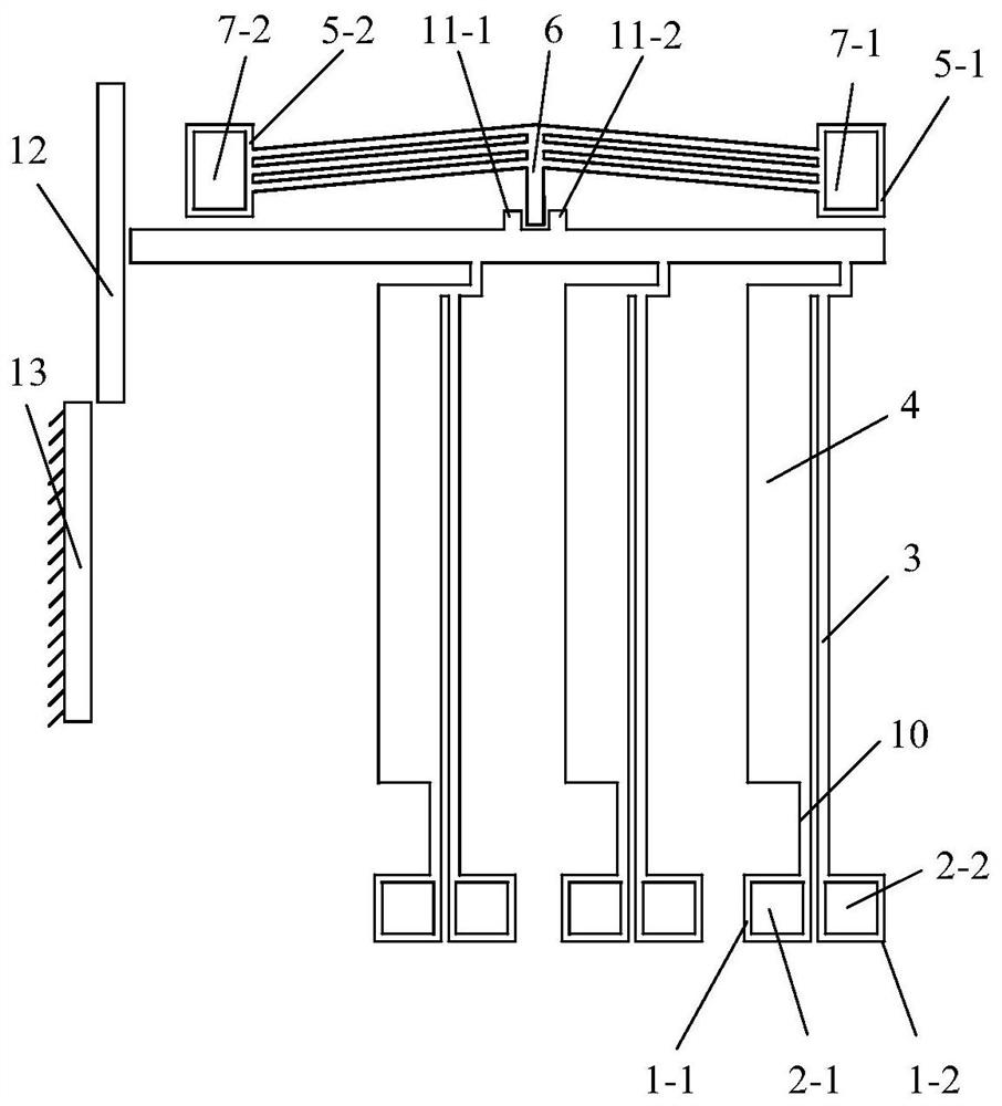
[0033] combine figure 1 , the present invention is based on the electrothermal micro-drive control optical path on-off device of U+V structure, including a driving mechanism and a locking mechanism;

[0034] The drive mechanism includes a driver composed of N U-shaped cantilever beams cascaded in phase, N pairs of U-shaped cantilever beam anchor points, and N pairs of U-shaped cantilever beam electrode patches; wherein, each U-shaped cantilever beam includes: located in the U-shaped structure The hot arm 3 on one side, the cold arm 4 and the flexible arm 10 on the other side of the U-shaped structure, wherein one end of the cold arm 4 is connected to one end of the hot arm 3, and the other end of the cold arm 4 is connected to one end of the flexible arm 10 ; Every pair of U-shaped cantilever beam anchor points includes a first anchor point 1-1 and a second anchor point 1-2, the other end of the flexible arm 10 is fixedly connected to the first anchor point 1-1, and the other ...

Embodiment 2

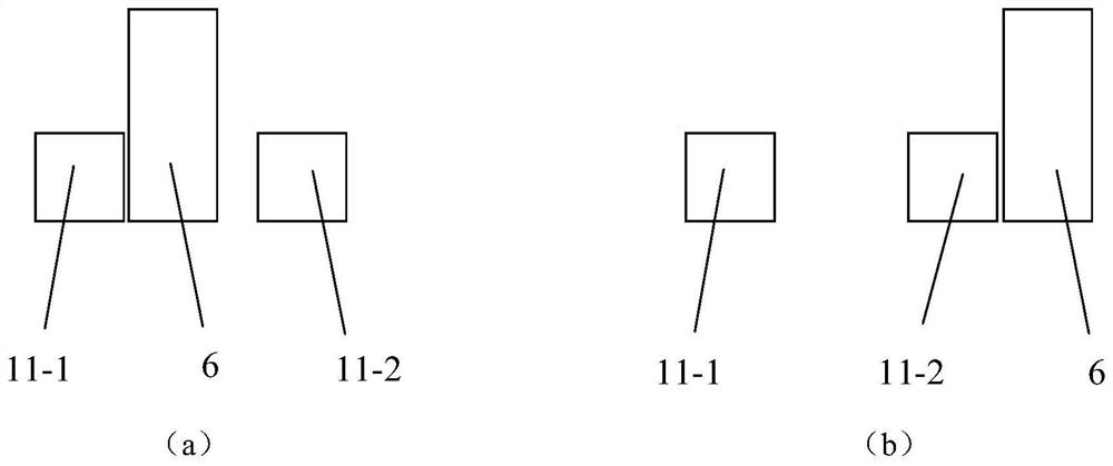
[0038] On the basis of Example 1, the thermal arm 3 located on one side of the U-shaped structure is a double thermal arm, including a first thermal arm 3-1 and a second thermal arm 3-2 in parallel, as Figure 6 As shown, one end of the first thermal arm 3-1 and one end of the second thermal arm 3-2 are connected to one end of the cold arm 4, and the other end of the first thermal arm 3-1 is fixedly connected to the second anchor point 1- 2. The other end of the second thermal arm 3-2 is fixed to the third anchor point 1-3, and the second anchor point 1-2 and the third anchor point 1-3 are respectively fixed to the second electrode patch 2-2 1. The first electrode patch 2-1.

[0039] The invention realizes the effective control of the optical path switch through the logical cooperation of the U-shaped cantilever beam electrothermal micro-drive mechanism and the V-shaped cantilever beam locking mechanism, and can further realize the effective on-off control of the high-energy o...


PUM

PropertyMeasurementUnit
angleaaaaaaaaaa

Abstract

The invention discloses an electrothermal micro-drive control optical path on-off device based on a U+V structure, and belongs to the technical field of MEMS micro-drivers. The device includes a driving mechanism and a locking mechanism, wherein the driving mechanism includes a driver composed of N U-shaped cantilever beams in cascade, N pairs of U-shaped cantilever beam anchor points, and N pairs of U-shaped cantilever beam electrode patches; the locking mechanism It includes a V-shaped cantilever beam array composed of M V-shaped cantilever beams, two V-shaped cantilever beam anchor points and two V-shaped cantilever beam electrode patches. By applying a voltage on the electrode sheet, the driving mechanism can be reliably locked in the non-driving or driving state, and the effective on-off control of the high-energy optical path can be realized. Compared with other micro-drive methods, the present invention adopts the logical cooperation of U-shaped cantilever beam electrothermal micro-drive mechanism and V-shaped cantilever beam locking mechanism, which has high driving reliability, low energy consumption, low cost and good system compatibility. A MEMS driver with excellent performance.

Description

technical field [0001] The invention belongs to the technical field of MEMS micro-drivers, in particular to an electrothermal micro-drive control optical path on-off device based on a U+V structure. Background technique [0002] MEMS micro-actuator is a key technology in micro-electromechanical systems, mainly including electrostatic drive, electromagnetic drive, electrothermal or thermal expansion drive, piezoelectric drive and intelligent material drive. Electrostatic drive uses the Coulomb force of electrostatic charge to generate attraction or repulsion to cause displacement of the driver. It has simple structure, convenient control, good system integration and manufacturability, large action stroke and high response frequency, but the required driving voltage is high, and the higher voltage It will cause the insulation layer between the electrode plates to be broken down, and long-term work will cause the accumulation of charges, which will affect the working stability ...

Claims


Application Information

Patent Timeline
Patent Type & Authority Patents(China)
IPC IPC(8): G02B26/08
CPCG02B26/0866
Inventor 王新杰赵海龙陈浩聂伟荣
Owner 徐州冀华机电科技有限公司
Why Eureka
Try Eureka