
Wet dust collection device for exhaust gas with dust

A technology for wet dedusting and waste gas, which is applied in the direction of mixer with rotating stirring device, mixing method, gas treatment, etc., to achieve the effect of reducing the limitation of use, prolonging the contact time and improving the adsorption effect

Inactive Publication Date: 2019-07-26
盐城国环睿保科技有限公司
View PDF0 Cites 0 Cited by
  • Summary
  • Abstract
  • Description
  • Claims
  • Application Information

AI Technical Summary

Problems solved by technology

[0002] As we all know, the soot and waste gas wet dedusting device is an auxiliary device for dust removal and purification of soot and waste gas, which has been widely used in the field of environmental protection; the existing soot and waste gas wet dedusting device includes a first base plate, a purification box, the first liquid pump, circulating water inlet pipe, circulating water spray pipe, drain pipe, air collecting hopper and exhaust pipe, the top of the first bottom plate is connected with the bottom of the purification box, and a chamber is arranged inside the purification box to purify The top of the box is provided with an upper opening, and the lower side of the left end of the purification box is provided with a left opening, and both the left opening and the upper opening communicate with the chamber. The left input end of the water pipe passes through the underside of the right end of the purification tank and extends into the chamber of the purification tank, the right output end of the circulating water inlet pipe is connected with the left input end of the first liquid pump, and the circulating spray pipe The bottom input end is connected with the top output end of the first liquid pump, the left end of the circulation spray pipe passes through the upper side of the right end of the purification tank and extends into the interior of the chamber, the left end of the circulation spray pipe is closed and the circulation spray pipe The left end is connected to the upper side of the inner wall on the left side of the chamber. The bottom end of the circulating water spray pipe located inside the chamber is provided with multiple groups of water spray holes horizontally. The right input end of the drain pipe passes through the lower side of the left end of the purification box and extends into the interior of the chamber, the drain pipe is provided with a first valve, and the first valve is located outside the purification box, the bottom output end of the air collection hopper communicates with the upper opening of the purification box, and the top output end of the air collection hopper is connected to the exhaust The bottom input end of the trachea is connected; when using the existing dust and waste gas wet dust removal device, first open the first valve and inject an appropriate amount of water into the chamber of the purification box through the drain pipe, then close the first valve, and then open the first liquid pump, the water passes through the circulating water inlet pipe, the first liquid pump and the circulating water spray pipe in turn, and is sprayed from top to bottom into the chamber of the purification box through multiple sets of water spray holes of the circulating water spray pipe. The external air supply device is connected, and the exhaust gas mixed with smoke and dust enters the chamber of the purification box through the left opening. Adsorb and fall to the bottom of the chamber to form a water circuit cycle. The purified air passes through the upper opening, the air collecting hopper and the exhaust pipe in turn, and is discharged to the outside through the top output end of the exhaust pipe; the existing soot and waste gas wet method During the use of the dust removal device, it was found that the waste gas mixed with smoke and dust has a short contact time with water, which affects the adsorption effect, and the water and air in the chamber of the purification box flow out more from the upper opening during the purification process, and it needs to be frequently poured into the chamber of the purification box. Supplementary water leads to high use limitations; and the contact area between the exhaust gas mixed with smoke and dust in the chamber of the purification box is small, and the adsorption effect is poor, resulting in poor practicability

Method used


Image

  • Wet dust collection device for exhaust gas with dust
  • Wet dust collection device for exhaust gas with dust
  • Wet dust collection device for exhaust gas with dust

Examples


Embodiment Construction

[0017] The specific implementation manners of the present invention will be further described in detail below in conjunction with the accompanying drawings and embodiments. The following examples are used to illustrate the present invention, but are not intended to limit the scope of the present invention.

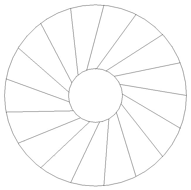
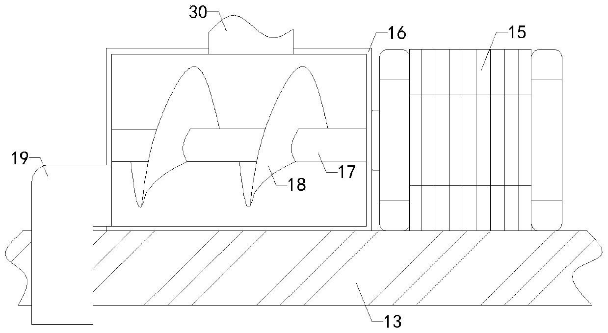
[0018] Such as Figure 1 to Figure 3As shown, a dust and waste gas wet dust removal device of the present invention includes a first bottom plate 1, a purification box 2, a first liquid pump 3, a circulating water inlet pipe 4, a circulating water spray pipe 5, a drain pipe 6, and an air collecting bucket 8 With the exhaust pipe 9, the top of the first bottom plate 1 is connected with the bottom end of the clean box 2, the inside of the clean box 2 is provided with a chamber, the top of the clean box 2 is provided with an upper opening, and the lower side of the left end of the clean box 2 is provided with a The left opening, and both the left opening and the upper openin...


PUM


Abstract

The invention relates to the technical field of environmental protection, in particular to a wet dust collection device for exhaust gas with dust. The wet dust collection device for exhaust gas with dust comprises a first bottom plate, a purifying box, a first liquid pump, a circulating water inlet pipe, a circulating water spraying pipe, a drain pipe, a gas collecting hopper, an exhaust pipe, a water feeding pipe, a second bottom plate, a storage box, a first motor, a conveying box, a discharge pipe, a liquid discharge pipe, a second liquid pump and a liquid conveying pipe, wherein the top end of the first bottom plate is connected to the bottom end of the purifying box, the bottom output end of the water feeding pipe extends into the bottom of a cavity, the left output end of the water feeding pipe penetrates through a left opening of the purifying box and extends out of the left end of the purifying box, the top end of the second bottom plate is connected to the bottom end of the storage box, and a working chamber is arranged in the storage box. The wet dust collection device for exhaust gas with dust has the advantages that time of contact between water and the exhaust gas withdust is prolonged to improve the adsorption effect, the frequency of supplementing the water into the cavity of the purifying box is decreased and limitations on use are lowered; the contact area between the exhaust gas with dust and the water in the cavity of the purifying box is increased, and accordingly the adsorption effect and practicability are both improved.

Description

technical field [0001] The invention relates to the technical field of environmental protection, in particular to a smoke and dust waste gas wet dust removal device. Background technique [0002] As we all know, the soot and waste gas wet dedusting device is an auxiliary device for dust removal and purification of soot and waste gas, which has been widely used in the field of environmental protection; the existing soot and waste gas wet dedusting device includes a first base plate, a purification box, the first liquid pump, circulating water inlet pipe, circulating water spray pipe, drain pipe, air collecting hopper and exhaust pipe, the top of the first bottom plate is connected with the bottom of the purification box, and a chamber is arranged inside the purification box to purify The top of the box is provided with an upper opening, and the lower side of the left end of the purification box is provided with a left opening, and both the left opening and the upper opening c...

Claims


Application Information

Patent Timeline
IPC IPC(8): B01D47/02B01F15/02B01F7/18B01F3/04
CPCB01D47/02B01D47/021B01D2258/0283B01F23/291B01F27/90B01F35/7175
Inventor 张蕾康正芳王旭
Owner 盐城国环睿保科技有限公司
Features
  • Generate Ideas
  • Intellectual Property
  • Life Sciences
  • Materials
  • Tech Scout
  • Unparalleled Data Quality
  • Higher Quality Content
  • 60% Fewer Hallucinations
Learn More