Method for generating micro-droplet by vibrating pipeline to control micro-fluidic chip

A microfluidic chip and micro-droplet technology, which is applied in fluid controllers, chemical instruments and methods, and laboratory containers, can solve the problems of difficult control of micro-droplet size and cost increase, and achieve particle size Consistent, productivity-enhancing, highly monodisperse effect

Inactive Publication Date: 2019-07-26
CHINA JILIANG UNIV
View PDF4 Cites 12 Cited by
  • Summary
  • Abstract
  • Description
  • Claims
  • Application Information

AI Technical Summary

Problems solved by technology

At present, there are several methods for microfluidic chips to generate size-controllable microdroplets: one is by changing the channel geometry of the microfluidic chip, but for the generation of microdroplets of different sizes, by changing the channel geometry, the Machining accuracy puts forward higher requirements, and the cost will also increase significantly
The second is to control the micro-droplets of different sizes by changing the viscosity and surface tension of the two fluids, but for a given fluid property, this method is difficult to control the size of the generated micro-droplets, thus limiting its application. Precisely control the pressure of the fluid to control the micro-droplets of different sizes, the fluid requires high pressure during operation, thus limiting the application of this method in the actual process
The above methods have more or less technical limitations and difficulties in the process of use, but if a stable mechanical disturbance is applied in the external dispersed phase pipeline, the microfluidic chip micro-droplet flow can be controlled. generated, which will solve the above problems to a large extent

Method used


Image

  • Method for generating micro-droplet by vibrating pipeline to control micro-fluidic chip
  • Method for generating micro-droplet by vibrating pipeline to control micro-fluidic chip

Examples


Embodiment Construction

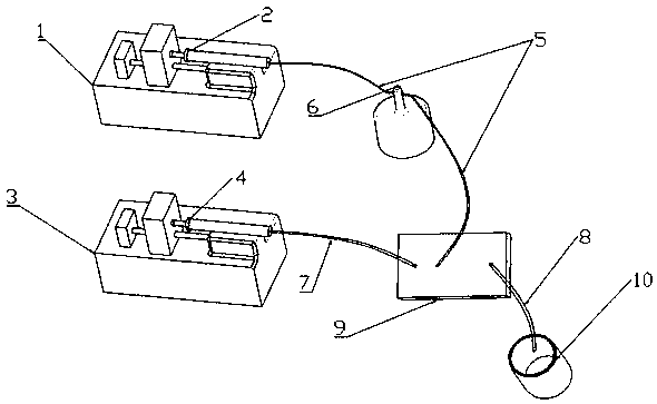
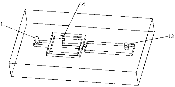
[0023] Such as figure 1 As shown, taking mechanical disturbance in the dispersed phase pipeline during the process of generating micro-droplets in the flow-focusing microfluidic chip as an example, the specific embodiment of the present invention is: at a certain continuous phase flow point Q 1 , to adjust the flow rate of the dispersed phase fluid Q 2 , making its flow rate just weaker than the critical flow rate for continuous droplet generation Q C , push the micro-sampler 2 through the syringe pump 1 to make the fluid enter the dispersed-phase pipeline 5 and pass through the electromagnetic vibrator 6 to make the fluid flow into the dispersed-phase inlet 12 in the flow-focused microfluidic chip 9 . The syringe pump 3 pushes the micro-sampler 4 so that the fluid enters the continuous phase pipeline 7 and flows into the continuous phase inlet 11 of the flow-focused microfluidic chip 9 . Two immiscible fluids meet in a narrow channel and touch each other, breaking apart...


PUM


Abstract

The invention discloses a method for generating a micro-droplet by vibrating a pipeline to control a micro-fluidic chip. The method comprises the following steps: selecting a certain type of the micro-fluidic chip, under a certain continuous phase flow point, adjusting flow of dispersion phase fluid, and enabling the flow thereof to be exactly weaker than critical flow in which droplets are continuously generated; applying one time of impact vibration with precision-adjustable amplitude and pulse number to a non-gas-phase fluid pipeline in upstream dispersion phase or continuous phase of a two-phase fluid inlet of the micro-fluidic chip through an electromagnetic vibrator; controlling a size of the micro-droplet generated in the micro-fluidic chip through the amplitude of the above impactvibration; and controlling the micro-fluidic chip to generate the single micro-droplet through a single impact wave-shaped pulse in the impact vibration; thereby generating the single or arbitrary number of the micro-droplets. The method is capable of actively controlling a generating size and frequency of the micro-droplet, and greatly improving production efficiency of the droplet.

Description

technical field [0001] The invention belongs to the field of fluid machinery, and relates to a method for controlling a microfluidic chip to generate microdroplets by a vibrating pipeline. Background technique [0002] In recent years, micro-droplet technology has received widespread attention due to its important influence in the field of scientific research and special applications in the field of engineering. Researchers have proposed many methods to form approximately monodisperse micro-droplets, such as dripping faucets, nozzle release, microfluidic technology and so on. Among these technologies, droplet microfluidics is the most common method, which can be used in food delivery, drug delivery, chemical reaction, health monitoring and some other bioanalysis fields. In general, there are three typical geometries that can be used to generate microdroplets: T-shaped, flow-focused, and coaxial-flow. Among them, the flow-focusing type can realize the formation of micro-dro...

Claims


Application Information

Patent Timeline
Patent Type & Authority Applications(China)
IPC IPC(8): B01L3/00
CPCB01L3/5027B01L3/50273B01L2200/10B01L2400/0433
Inventor 金积君凃程旭包福兵尹招琴叶煜航
Owner CHINA JILIANG UNIV
Why Eureka
Try Eureka