Magnetic suspension bearing stator, magnetic suspension bearing, motor, compressor and air conditioner

A bearing stator and magnetic suspension technology, which is applied in the fields of magnetic suspension bearing stator, motor, magnetic suspension bearing, compressor and air conditioner, can solve the problems of shell deformation, low reliability and unsatisfactory coaxial accuracy, and achieves the reduction of The amplitude of small high-frequency vibration, improving the matching accuracy, and avoiding the effect of multiple disassembly and assembly

Pending Publication Date: 2019-07-26
GREE ELECTRIC APPLIANCES INC OF ZHUHAI +1
View PDF1 Cites 0 Cited by
  • Summary
  • Abstract
  • Description
  • Claims
  • Application Information

AI Technical Summary

Problems solved by technology

[0005] 1. Since the shell is made of aluminum alloy and the connecting ring is made of steel, the hardness of the shell material is lower than that of the connecting ring, which will cause irreversible plastic deformation of the shell during shrink-fit assembly, resulting in an interference fit that cannot meet the requirements
In particular, the shell and the connecting ring may not meet the requirements after installation, and a second disassembly and assembly is required. After the shell and the connecting ring are disassembled and assembled many times, the shell is seriously deformed, which affects the coaxial accuracy of the magnetic levitation assembly and is not conducive to the suspension of the rotor. control, and may even cause the entire magnetic bearing assembly to be scrapped and unusable, which will bring great loss and inconvenience to product maintenance
[0006] 2. After the plastic deformation of the shell, the actual interference cannot meet the requirements. During the operation, the magnetic suspension bearing needs to adjust the electromagnetic force of the stator winding in real time according to the feedback of the rotor position signal, so as to realize the rotor in the Fixed position frictionless high speed rotation
Due to the constant change of the electromagnetic force, the stator core and the connecting ring are subjected to the reaction force of the electromagnetic force, and small displacement vibrations of different frequencies will be made in the housing. At the resonant frequency and critical speed, the vibration displacement shows an exponential growth. After running for a long time, the connecting ring, stator core and shell will be loose, the magnetic suspension bearing cannot be use

Method used


Image

  • Magnetic suspension bearing stator, magnetic suspension bearing, motor, compressor and air conditioner
  • Magnetic suspension bearing stator, magnetic suspension bearing, motor, compressor and air conditioner
  • Magnetic suspension bearing stator, magnetic suspension bearing, motor, compressor and air conditioner

Examples


Example Embodiment

[0048] Example one of magnetic suspension bearing stator, magnetic suspension bearing, motor, compressor and air conditioner:

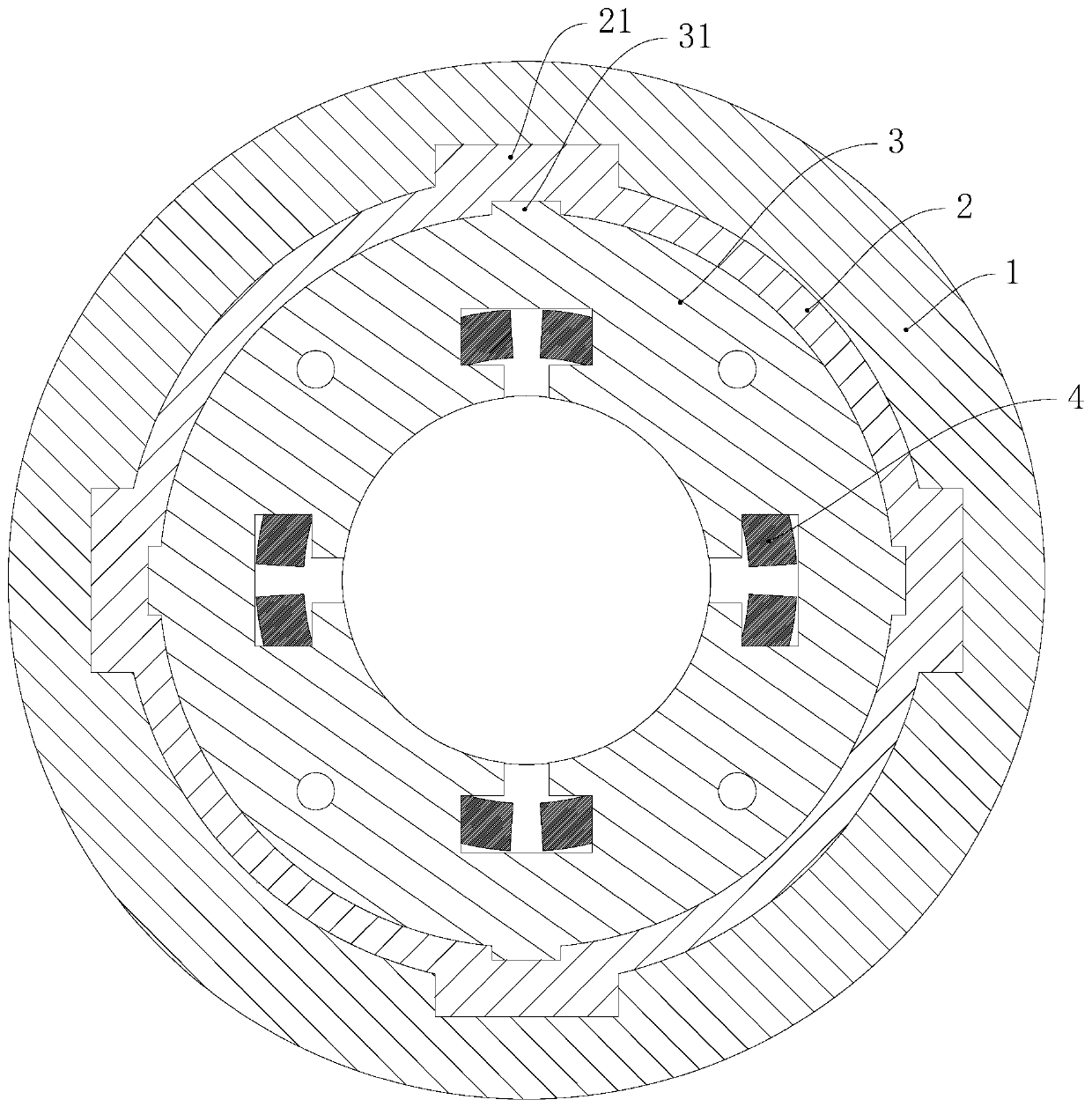
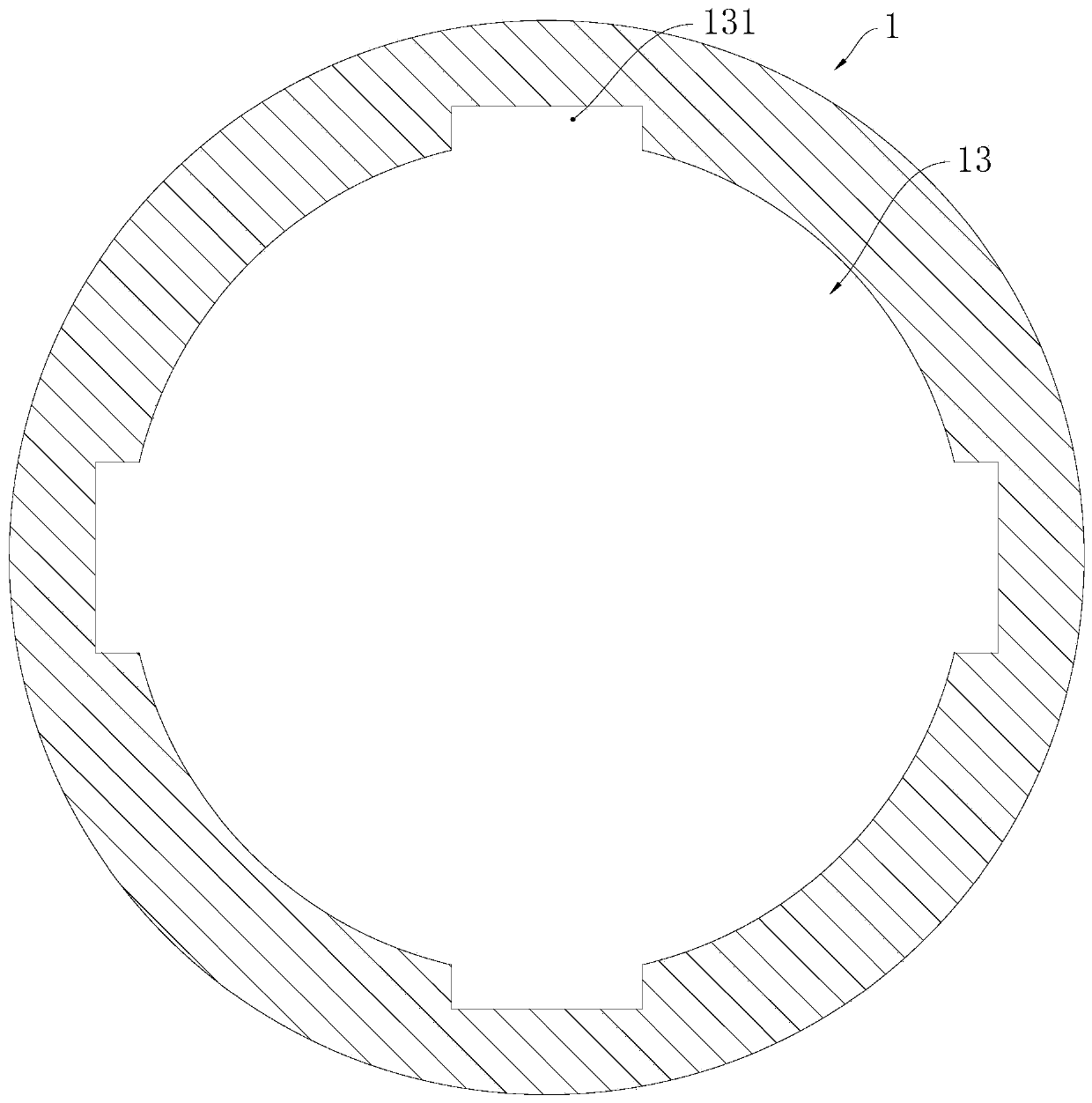
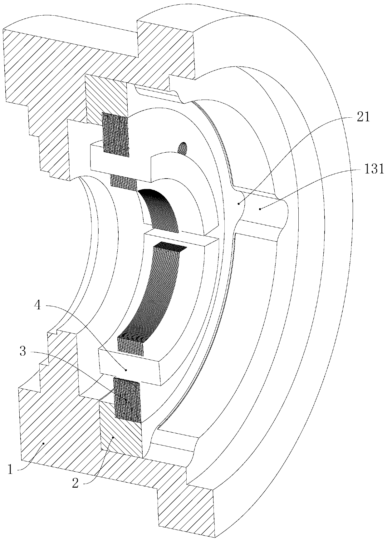
[0049] The air conditioner of this embodiment uses the compressor of this embodiment, the compressor of this embodiment includes the magnetic suspension bearing of this embodiment, the motor of this embodiment includes the magnetic suspension bearing of this embodiment, and the magnetic suspension bearing of this embodiment includes a rotor and The magnetic suspension bearing stator of this embodiment. Please refer to Figure 1 to 4 The magnetic bearing stator of this embodiment includes a housing 1 and a stator assembly. The housing 1 has an installation cavity 13 in which the stator assembly is installed.

[0050] Please refer to figure 1 and Figure 4 The stator assembly includes a connecting ring 2, a stator core 3 and a stator winding 4. The stator winding 4 is wound on the stator core 3. The outer peripheral wall of the stator core 3 and the inner p...

Example Embodiment

[0059] The second embodiment of magnetic suspension bearing stator, magnetic suspension bearing, compressor and air conditioner:

[0060] Please refer to Figure 5 and Image 6 In the magnetic bearing stator of this embodiment, along the axial direction of the magnetic bearing stator, the mounting cavity 13 is formed between the first side wall 11 and the second side wall 12. The stator assembly is installed in the mounting cavity 13, and the One end in the axial direction abuts against the first side wall 11, and the other end of the stator assembly in the axial direction abuts against the second side wall 12. The first side wall 11 and the second side wall 12 restrict the movement of the stator assembly in the axial direction. Specifically, after the assembly of the stator assembly is completed, the housing 1 is formed on the stator assembly by die casting, and the housing 1 is cooled and shrunk to achieve the purpose of interference fit between the housing 1 and the connecting ...


PUM


Abstract

The invention discloses a magnetic suspension bearing stator, a magnetic suspension bearing, a motor, a compressor and an air conditioner, and relate to the field of air conditioners. The magnetic suspension bearing stator comprises a shell and a stator assembly, wherein the shell is provided with a mounting cavity, the stator assembly comprises a connecting ring, the outer circumferential wall ofthe connecting ring is in interference fit with the circumferential wall of the mounting cavity, a first positioning bulge and a first positioning groove are arranged between the connecting ring andthe shell, the first positioning bulge is embedded in the first positioning groove, in the circumferential direction of the connecting ring, the first positioning bulge is abutted against the groove wall of the first positioning groove, the first positioning bulge is arranged on the outer circumferential wall of the connecting ring, and the first positioning groove is formed in the circumferentialwall of the mounting cavity. The assembling difficulty of the stator assembly and the shell is low, and the mounting precision is high; the matching reliability between the connecting ring and the shell is high, even if the magnetic suspension bearing stator operates under a high-temperature working condition, the stator assembly can not shake relative to the shell in the circumferential direction, so that looseness of the stator assembly relative to the shell is avoided, and the system rigidity of the magnetic suspension bearing stator is improved.

Description

technical field [0001] The invention relates to the field of air conditioning, in particular to a magnetic suspension bearing stator, a magnetic suspension bearing, a motor, a compressor and an air conditioner. Background technique [0002] Magnetic suspension bearings use magnetic force to suspend the rotor in the air, so that there is no mechanical contact between the rotor and the stator. A conventional magnetic suspension bearing stator includes: a stator winding, a stator core, a connecting ring and a casing. [0003] Among them, the stator winding is enameled wire, which mainly provides electromagnetic force for the magnetic suspension bearing. The stator core is made of magnetic silicon steel sheet material, which is mainly used for the placement of the stator winding and the conduction of the magnetic circuit. Together with the magnetic suspension bearing rotor and air gap, it forms a complete electromagnetic circuit. The connecting ring is a magnetically conductiv...

Claims


Application Information

Patent Timeline
IPC IPC(8): F16C32/04
CPCF16C32/044
Inventor 伍尚权龚敏龙胜民王周叶林学明张核
Owner GREE ELECTRIC APPLIANCES INC OF ZHUHAI
Why Eureka
Try Eureka