Laser emitting device
A technology for light-emitting devices and lasers, applied in lighting devices, light guides for lighting devices, fixed lighting devices, etc., can solve the problems of rising maintenance costs and inconvenient maintenance, and achieve enhanced reliability, guaranteed aging resistance and life, and centralized maintenance. Convenient and fast effects
- Summary
- Abstract
- Description
- Claims
- Application Information
AI Technical Summary
Problems solved by technology
Method used
Image
Examples
no. 1 approach
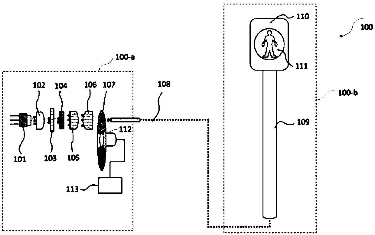
[0030] The laser light emitting device in the present invention generally consists of three parts: a light source control part, a light transmission part and a terminal part, wherein the light source control part and the terminal part are set separately. figure 1 A first embodiment in which the laser light emitting device of the present invention is applied to the traffic light system 100 is shown.
[0031] exist figure 1 In the illustrated embodiment, the light source control unit 100a is a light source control unit built in a non-harsh environment (such as indoors), and it can also be placed at the bottom of the traffic lights or set on the ground. For the selection of the construction site, those skilled in the art can select a suitable area according to factors such as the region or the specific requirements of the system using the laser light emitting device, which will not be repeated in the present invention. Compared with the harsh outdoor environment, the indoor envi...
Embodiment 1
[0066] Such as Image 6 As shown, the wavelength selection part 107 is a wavelength selection dial, and the wavelength selection area therein is a fan-shaped area, and the angle corresponding to each fan-shaped area can be adjusted according to the light-emitting time of each corresponding color. exist Image 6 In the illustration, the wavelength selection unit 107 includes four wavelength selection regions as an example for description.
[0067] exist Image 6 Among them, the wavelength selection part 107 includes a green wavelength selection region a, two yellow wavelength selection regions c and a red wavelength selection region b, wherein the yellow wavelength selection region c is sandwiched between the green wavelength selection region a and the red wavelength selection region between light wavelength selective regions b. By adjusting the rotational speed of the wavelength selection turntable and the angle corresponding to the wavelength selection area, the required l...
no. 2 approach
[0097] Figure 13 A second embodiment in which the laser light emitting device of the present invention is applied to a traffic light system 200 is shown.
[0098] The same parts in the second embodiment and the first embodiment are described with the same reference numerals, and the detailed description of the same parts is omitted, and only the difference between the second embodiment and the first embodiment will be described below.
[0099] see Figure 13 , the traffic light system 200 includes a light source module 201 , a wavelength selection unit 207 , an optical transmission unit 108 and a terminal unit 202 . and figure 1 By comparison, it can be seen that one light source module is used to control a single traffic light in the first embodiment, while two light source modules 201 are used in the second embodiment, and the two light source modules 201 use the same wavelength selection part 207, and respectively control two terminal parts (traffic lights) of the inter...
PUM
 Abstract
Description
Claims
Application Information
 - R&D
- Intellectual Property
- Life Sciences
- Materials
- Tech Scout
- Unparalleled Data Quality
- Higher Quality Content
- 60% Fewer Hallucinations
Browse by: Latest US Patents, China's latest patents, Technical Efficacy Thesaurus, Application Domain, Technology Topic, Popular Technical Reports.
© 2025 PatSnap. All rights reserved.Legal|Privacy policy|Modern Slavery Act Transparency Statement|Sitemap|About US| Contact US: help@patsnap.com


