Erect image system and binocular laser ranging telescope

A telescope and erection technology, applied in telescopes, radio wave measurement systems, optics, etc., can solve the problems of user inconvenience, heavier weight, and increased telescope size, and achieve improved stability and reliability, easy to carry and use, The effect of reducing the volume

Active Publication Date: 2019-07-26
LANHAI PHOTOELECTRICITY TECH CO LTD
View PDF4 Cites 9 Cited by
  • Summary
  • Abstract
  • Description
  • Claims
  • Application Information

AI Technical Summary

Problems solved by technology

[0003] The range-finding telescope is an important branch of the range-finder. At present, the laser light path and the visible light path of the laser range-finding telescope are divided into two independent light paths, so that the telescope can only be used as a laser rangefinder sight and cannot be used for observation. Simultaneous ranging
The reason is: the measured distance cannot be displayed in the field of view of the telescope, which brings a lot of inconvenience to the user
At the same time, the optical components of the product to achieve observation and ranging are independent, just like a combination of building blocks, resulting in increased volume and weight of the telescope product, which is not easy to carry or operate

Method used


Image

  • Erect image system and binocular laser ranging telescope
  • Erect image system and binocular laser ranging telescope
  • Erect image system and binocular laser ranging telescope

Examples


Embodiment Construction

[0031] The following will clearly and completely describe the technical solutions in the embodiments of the present invention with reference to the accompanying drawings in the embodiments of the present invention. Obviously, the described embodiments are only some, not all, embodiments of the present invention. Based on the embodiments of the present invention, all other embodiments obtained by persons of ordinary skill in the art without making creative efforts belong to the protection scope of the present invention.

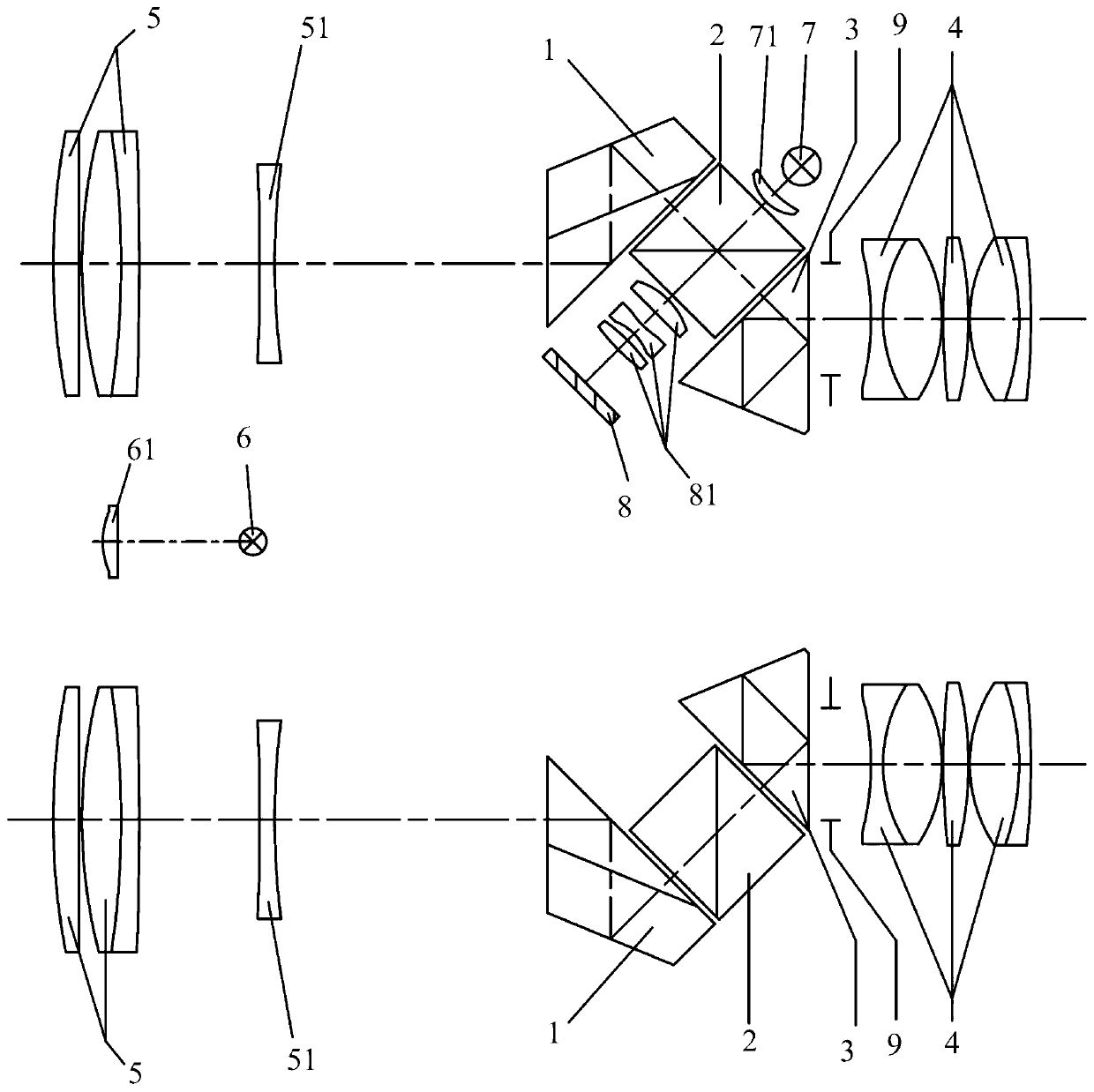
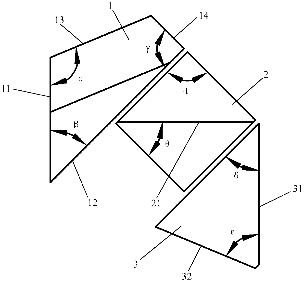
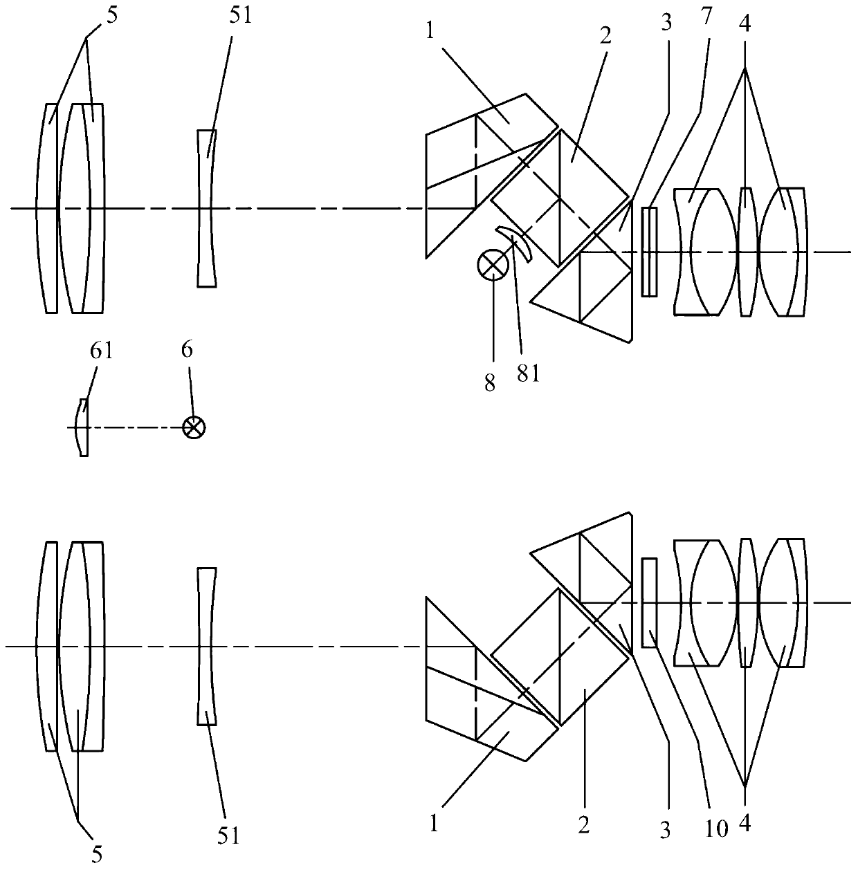
[0032] Please refer to the attached figure 1 , the present invention provides a kind of positive image system, comprising roof half pentaprism 1, dichroic prism 2 and isosceles prism 3; Two right-angle prisms are glued together, and a light-splitting film 21 is arranged on the glued surface of the two right-angle prisms.

[0033] The dichroic prism 2 is a square structure, and the inclined surfaces of the two isosceles right-angled prisms are bonded and conne...


PUM


Abstract

The invention discloses an erect image system and a binocular laser ranging telescope, wherein the erect image comprises a roof half pentaprism, a beam splitter prism and an isosceles prism; the beamsplitter prism is located between the roof half pentaprism and the isosceles prism, the beam splitter prism is formed by two rectangular prisms through agglutination, and an agglutination face of thetwo rectangular prisms is provided with a beam splitting film. The erect image system and the binocular laser ranging telescope provided by the invention are simple in structure and small in size, moreover, are convenient to use, can realize binocularly observing and aiming at a measured object, and while observing the object, can display distance to the measured object in real time in the field of view.

Description

technical field [0001] The invention belongs to the technical field of laser ranging, and more specifically relates to an erect image system and a binocular laser ranging telescope. Background technique [0002] The range finder is an instrument designed for length and distance measurement by using the characteristics of light, sound, electromagnetic wave reflection and interference. On the basis of length measurement, the new rangefinder can use the length measurement results to perform scientific calculations on the area, perimeter, volume, quality and other parameters of the target to be measured. It is widely used in engineering applications, GIS surveys, military and other fields. scope of application. [0003] The range-finding telescope is an important branch of the range-finder. At present, the laser light path and the visible light path of the laser range-finding telescope are divided into two independent light paths, so that the telescope can only be used as a las...

Claims


Application Information

Patent Timeline
Patent Type & Authority Applications(China)
IPC IPC(8): G02B27/10G02B23/04G01S17/08
CPCG01S17/08G02B23/04G02B27/1006
Inventor 钱向伟刘崇求
Owner LANHAI PHOTOELECTRICITY TECH CO LTD
Why Eureka
Try Eureka