
Broadband electrostatic micro-energy collector and collection system, and preparation method of collector

A collection system and micro-energy technology, applied in induction generators and other directions, can solve the problems of large vibrator mass of energy harvester, narrow energy collection frequency range, and unadjustable resonance frequency, achieving adjustable resonance frequency and wide application range. , the effect of easy miniaturization

Active Publication Date: 2019-07-26
TONGJI UNIV
View PDF6 Cites 2 Cited by
  • Summary
  • Abstract
  • Description
  • Claims
  • Application Information

AI Technical Summary

Problems solved by technology

However, the flexible piezoelectric sensor obtained by this patented technology does not have the function of free expansion and contraction in the length direction, and its resonance frequency cannot be adjusted, resulting in a narrow frequency range for energy harvesting, which is not conducive to improving its energy harvesting efficiency.
In addition, if the finished device prepared by using this patented technology wants to achieve higher output power, it needs to exert a large force on it, that is, as an energy harvester, it needs a larger vibrator mass, which makes the finished device difficult to miniaturize

Method used


Image

  • Broadband electrostatic micro-energy collector and collection system, and preparation method of collector
  • Broadband electrostatic micro-energy collector and collection system, and preparation method of collector
  • Broadband electrostatic micro-energy collector and collection system, and preparation method of collector

Examples


Embodiment 1

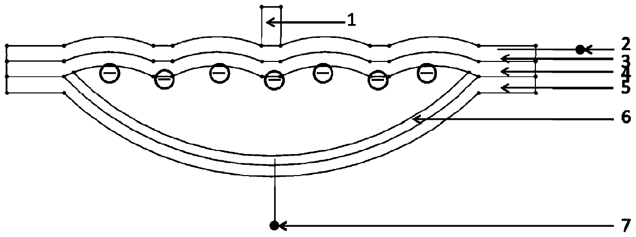
[0049] A broadband electrostatic micro-energy harvester, such as figure 1 As shown, the upper electrode 3, the high elastic polymer film 4, the lower electrode 6 and the bracket 5 are arranged in sequence, and the mass 1 fixedly bonded to the middle position of the upper electrode 3, and the upper electrode lead 2 connected to the upper electrode 3 and the lower electrode lead 7 connected to the lower electrode 6; the upper electrode 3 and the high elastic polymer film 4 are bonded and connected; the middle part of the support 5 is provided with a groove in the direction away from the high elastic polymer film 4, and the groove is an arc shaped groove; the two ends of the bracket 5 are attached to the high elastic polymer film 4; the lower electrode 6 is attached to the inside of the groove; a cavity is formed between the lower electrode 6 and the high elastic polymer film 4.

[0050]The specific materials and processing methods of each part in this embodiment are: one side su...

Embodiment 2

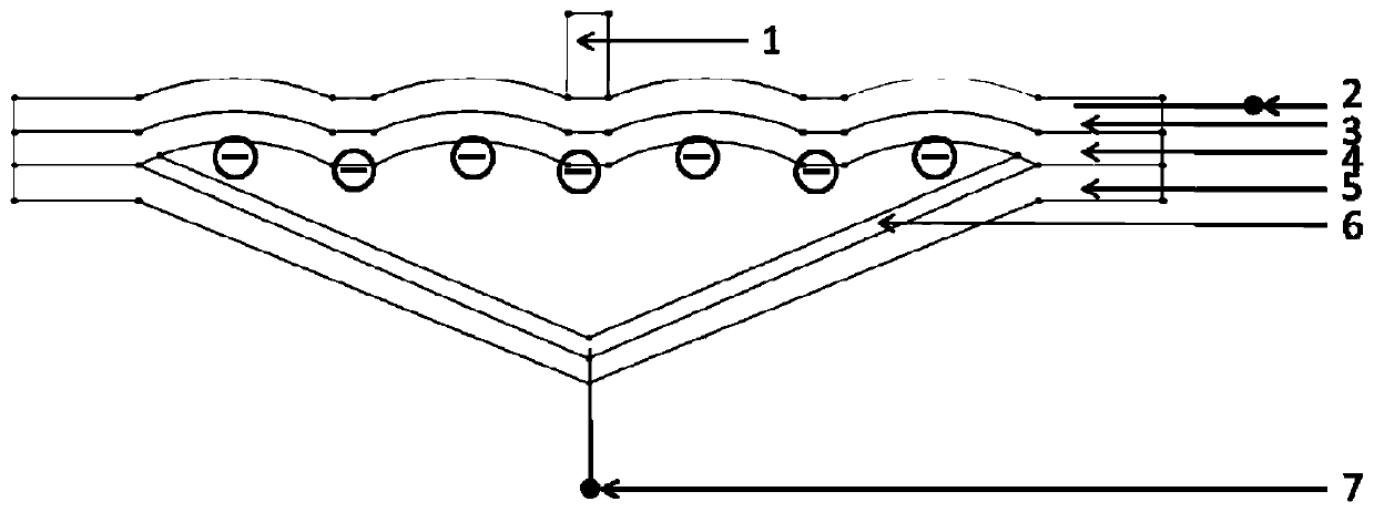
[0058] A broadband electrostatic micro-energy harvester, such as figure 2 As shown, the upper electrode 3, the high elastic polymer film 4, the lower electrode 6 and the bracket 5 are arranged in sequence, and the mass 1 fixedly bonded to the middle position of the upper electrode 3, and the upper electrode lead 2 connected to the upper electrode 3 and the lower electrode lead 7 connected to the lower electrode 6; the upper electrode 3 and the high elastic polymer film 4 are bonded and connected; the middle part of the bracket 5 is provided with a groove in the direction away from the high elastic polymer film 4, and the groove is triangular The groove; the two ends of the bracket 5 are attached and connected with the high elastic polymer film 4; the lower electrode 6 is attached inside the groove; a cavity is formed between the lower electrode 6 and the high elastic polymer film 4.

[0059] The specific materials and processing methods of each part in this embodiment are: on...

Embodiment 3

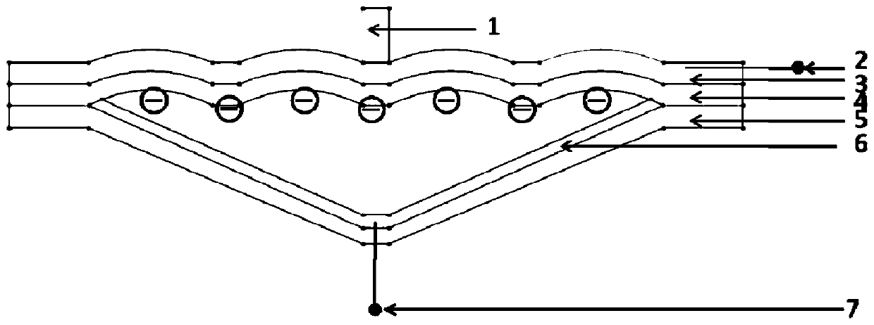
[0067] A broadband electrostatic micro-energy harvester, such as image 3 As shown, the upper electrode 3, the high elastic polymer film 4, the lower electrode 6 and the bracket 5 are arranged in sequence, and the mass 1 fixedly bonded to the middle position of the upper electrode 3, and the upper electrode lead 2 connected to the upper electrode 3 and the lower electrode lead 7 connected to the lower electrode 6; the upper electrode 3 and the high elastic polymer film 4 are bonded and connected; the middle part of the bracket 5 is provided with a groove in the direction away from the high elastic polymer film 4, and the groove is trapezoidal The groove; the two ends of the bracket 5 are attached and connected with the high elastic polymer film 4; the lower electrode 6 is attached inside the groove; a cavity is formed between the lower electrode 6 and the high elastic polymer film 4.

[0068] The specific materials and processing methods of each part in this embodiment are: on...


PUM


Abstract

The invention relates to a broadband electrostatic micro-energy collector and collection system, and a preparation method of the collector. The broadband electrostatic micro-energy collector comprisesan upper electrode, a high-elasticity polymer film, a lower electrode and a support arranged in sequence, a mass block fixedly bonded to the middle of the upper electrode, an upper electrode lead connected with the upper electrode and a lower electrode lead connected with the lower electrode; the upper electrode is connected with the high-elasticity polymer film in an attached mode; the middle ofthe support is provided with a groove in a direction away from the high-elasticity polymer film; the two ends of the support are connected with the high-elasticity polymer film in an attached mode; the lower electrode is attached to the interior of the groove; and a cavity is formed between the lower electrode and the high-elasticity polymer film. Compared with the prior art, the collector has the advantages of being simple in structure, adjustable in resonant frequency, wide in frequency band and the like, and can be used for environmental vibration energy collection, human motion energy collection and the like.

Description

technical field [0001] The invention relates to the technical field of functional devices, in particular to a broadband electrostatic micro-energy collector. Background technique [0002] With the continuous development of MEMS technology and integrated circuit technology, great progress has been made in the research and development of microelectronic devices with small size and low power consumption. However, the development of related micro-energy technology is relatively lagging behind. At the same time, due to the disadvantages of large chemical battery size, limited life and need to be replaced, the application in some microelectronic products is limited, especially for the current rapid development of wireless sensors. Network and embedded systems, this defect will be more obvious. Utilizing the vibration energy with high energy density ubiquitous in nature and converting it into electrical energy, and then providing continuous electrical energy for low-power electron...

Claims


Application Information

Patent Timeline
IPC IPC(8): H02N1/08
CPCH02N1/08
Inventor 张晓青马星晨
Owner TONGJI UNIV
Learn More