
Automatic austempered grinding ball forming and producing equipment

A technology of automatic molding and production equipment, which is applied to casting molding equipment, equipment for transporting molds, equipment for feeding molten metal into molds, etc. Product production efficiency and other issues, to achieve the effect of improving production efficiency, avoiding the misalignment of upper and lower molds, and improving the pass rate

Pending Publication Date: 2019-07-30
CHENGDE RONGMAO CAST STEEL +1
View PDF0 Cites 0 Cited by
  • Summary
  • Abstract
  • Description
  • Claims
  • Application Information

AI Technical Summary

Problems solved by technology

[0004] 1. The 8 stations of the steel mold on the production equipment move cyclically. Affected by the vibration of the movement, it is difficult to avoid a slight misalignment between the upper and lower molds. In addition, it is difficult to avoid local damage to the runner system, which makes it difficult to ensure the pouring of the product Quality, which in turn leads to a reduction in the pass rate of the product
[0005] 2. Due to the closed-loop production mode, once a certain station has a problem and needs to be repaired and maintained, the entire production line must stop working, which cannot guarantee the continuous productivity of the product, which affects the production efficiency of the product
[0006] 3. Since the sand mold needs to be covered and cleaned in the mold cavity before and after the grinding ball is formed, the production cost is high and the environment is polluted
[0007] No technical solution similar to this patent was found after searching the prior art

Method used


Image

  • Automatic austempered grinding ball forming and producing equipment
  • Automatic austempered grinding ball forming and producing equipment
  • Automatic austempered grinding ball forming and producing equipment

Examples


Embodiment Construction

[0034] The present invention will be further described in detail below in conjunction with the accompanying drawings and through specific embodiments. The following embodiments are only descriptive, not restrictive, and cannot limit the protection scope of the present invention.

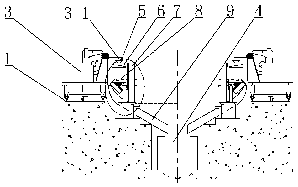
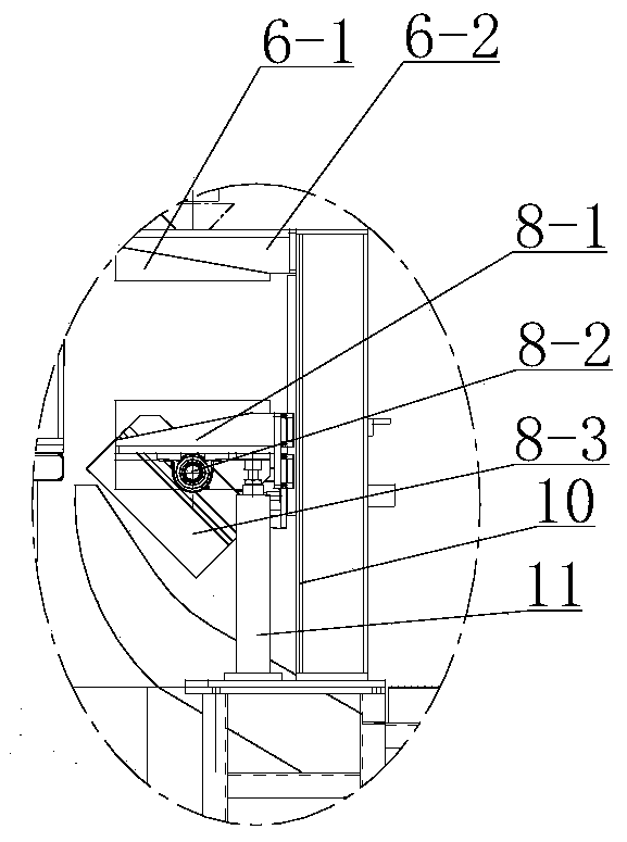
[0035] A kind of Aubei grinding ball automatic forming production equipment, please refer to Figure 1-10 , its invention point is:

[0036] It includes a conveying track 1 arranged in a straight line, and a pouring machine 3 that can move along the conveying track is installed above the conveying track. The pouring outlet of the pouring machine protrudes from the side above the conveying track, and is parallel to A plurality of pouring positions are arranged at intervals in the direction of the conveying track to form a pouring line 2 . Each pouring position is all equipped with a steel mold support 7, and upper fixed mold 6 and the lower movable mold 8 that can realize moving up and down and tippi...


PUM


Abstract

The invention relates to automatic austempered grinding ball forming and producing equipment. Conveying tracks are included. A pouring machine is arranged above each conveying track. A pouring outputport of each pouring machine stretches out of one side of the upper portion of the corresponding conveying track, the side of each conveying track is externally provided with a plurality of pouring positions in the direction parallel to the conveying track at intervals, and a pouring line is formed. A steel die support is arranged at each pouring position and provided with an upper fixed die and alower movable die, wherein in the die assembly state, a plurality of grinding ball forming cavities are formed between the two dies, a pouring gate is arranged in the upper fixed die and the lower movable die and communicates with the grinding ball forming cavities and the upper end of the upper fixed die, and a pouring cup is arranged above the pouring gate. The pouring machines move to the positions right opposite to the pouring positions, the pouring output ports are in up-down linkage with the pouring cups. The lower position, corresponding to each lower movable die, of the correspondingpouring position is provided with a slide carriage, the slide carriages are outwards obliquely arranged in the direction away from the corresponding conveying tracks, and a conveyor is arranged beloweach slide carriage. By means of the equipment, the product pouring quality is guaranteed, and high production efficiency is achieved.

Description

technical field [0001] The invention belongs to the application field of the technical field of Aubei grinding ball production, and in particular relates to an automatic forming production equipment of Aubei grinding balls. Background technique [0002] At present, grinding balls have been widely used in metallurgy, mining, cement and other industries. Since the grinding ball is a consumable item, with the development of the industry, the consumption is increasing. Among them, the microstructure is austenite, bainite, spherical graphite and carbide grinding ball, which can be called Aobei grinding ball, which is a special grinding ball for ball mill. The current production methods of this kind of grinding balls are: sand casting molding production, iron mold sand-covered casting molding production. Compared with sand casting production, iron mold sand-covered casting production has the advantages of high production efficiency and has become the main production mode. The e...

Claims


Application Information

Patent Timeline
IPC IPC(8): B22D47/00B22C9/20B22C9/06B22D35/04B22D33/04B22D29/06
CPCB22D47/00B22C9/20B22C9/06B22D35/04B22D33/04B22D29/06
Inventor 王景荣王井会姜延飞李国禄凌利超孙树国王景利
Owner CHENGDE RONGMAO CAST STEEL
Learn More