Sludge centrifugal dewatering equipment and using method

A centrifugal dehydration and sludge technology, applied in chemical instruments and methods, water/sludge/sewage treatment, sludge treatment, etc., can solve the problems of long treatment cycle, difficult to move, complicated equipment, etc., to facilitate replacement and maintenance, speed up Water filtration process, the effect of improving feeding efficiency

Pending Publication Date: 2019-08-02
CHANGJIANG SURVEY PLANNING DESIGN & RES +1
View PDF8 Cites 0 Cited by
  • Summary
  • Abstract
  • Description
  • Claims
  • Application Information

AI Technical Summary

Problems solved by technology

[0002] There are a large number of reservoirs built in our country. After decades of operation, the silt at the bottom of the reservoir has accumulated continuously, encroaching on the reservoir capacity and reducing the operating efficiency of the reservoir. Therefore, it is very necessary to dredge the bottom of the reservoir, which can be directly restored. At the same time, drying the dredged material after dredging the bottom of the reservoir also has great economic benefits. However, according to the survey, there is currently no special equipment for dredging and drying the bottom of the reservoir. Most of the industrial sludge treatment equipment such as the belt-type roller press sludge water separator is operated in a factory, and there are problems such as complex equipment, large scale, long treatment cycle and difficulty in moving; the centrifugal dryer is mainly used in light industries such as clothing washing and printing and dyeing processing. There are problems such as discontinuous process, small processing capacity and inability to automatically discharge materials, which are not suitable for the application of drying treatment engineering of dredging material at the bottom of the reservoir

Method used


Image

  • Sludge centrifugal dewatering equipment and using method
  • Sludge centrifugal dewatering equipment and using method

Examples


Embodiment Construction

[0036] The implementation of the present invention will be described in detail below in conjunction with the accompanying drawings, but they do not constitute a limitation to the present invention, they are only examples, and at the same time, the advantages of the present invention will become clearer and easier to understand.

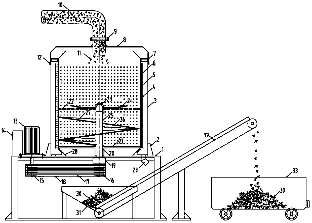
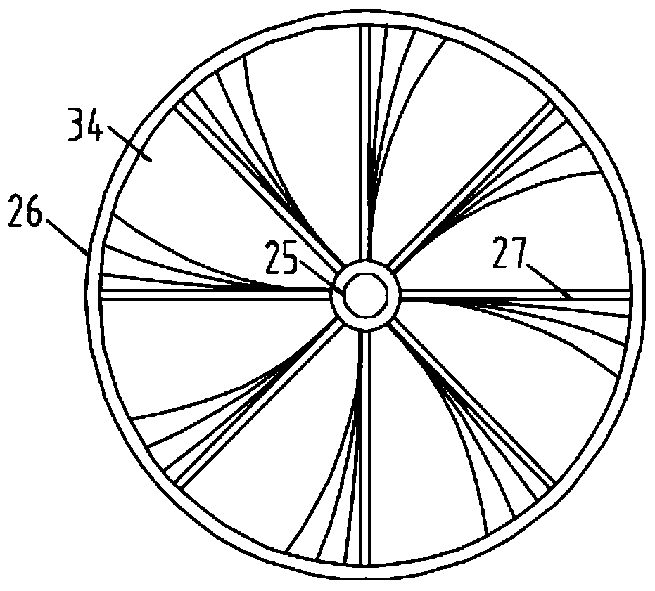
[0037] refer to Figure 1-2Shown: a sludge centrifugal dewatering equipment, which includes a machine base 1, a fixed ring 2, a water collection bucket 3, an outer filter bucket 4, a middle geotechnical filter 5, an inner filter bucket 6, a balance ring 7, a top cover 8, Flange 9, imported pumping steel pipe 10, dredging material 11, lock 12, motor 13, control cabinet 14, drive wheel 15, transmission wheel 16, transmission belt 17, transmission protection cover 18, electromagnetic clutch 19, filter bucket shaft 20. Lower connecting rod 21, upper connecting rod 22, spherical steel cover 23, tray 24, spiral scraper shaft 25, spiral scraper 26, spiral co...


PUM


Abstract

The invention discloses sludge centrifugal dewatering equipment and a using method. A water collecting bucket (3) is fixed on a machine base (1); an electric motor (13) is arranged on one side of themachine base (1); a control cabinet (14) is arranged on one side of the electric motor (13); the control cabinet (14) is connected with the electric motor (13) through a wire; a driving wheel (15) anda transmitting wheel (16) are arranged below the machine base (1); the driving wheel (15) is located below the electric motor (13); a transmitting belt (17) is arranged between the driving wheel (15)and the transmitting wheel (16); and the outer side of the transmitting belt (17) is sleeved with a transmission protection cover (18). The invention solves the problems that no special equipment fordewatering and drying treatment of bottom sediment exists in the prior art, and similar industrial sludge treatment equipment, centrifugal driers and other device are not applicable to the dewateringand drying treatment of the bottom sediment of a reservoir in engineering.

Description

technical field [0001] The invention relates to the technical field of hydraulic construction, in particular to a sludge centrifugal dewatering device and a use method thereof. Background technique [0002] There are a large number of reservoirs built in our country. After decades of operation, the silt at the bottom of the reservoir has accumulated continuously, encroaching on the reservoir capacity and reducing the operating efficiency of the reservoir. Therefore, it is very necessary to dredge the bottom of the reservoir, which can be directly restored. At the same time, drying the dredged material after dredging the bottom of the reservoir also has great economic benefits. However, according to the survey, there is currently no special equipment for dredging and drying the bottom of the reservoir. Most of the industrial sludge treatment equipment such as the belt-type roller press sludge water separator is operated in a factory, and there are problems such as complex equ...

Claims


Application Information

Patent Timeline
Patent Type & Authority Applications(China)
IPC IPC(8): C02F11/127C02F11/126
CPCC02F11/127C02F11/126
Inventor 谭界雄彭琦谭政
Owner CHANGJIANG SURVEY PLANNING DESIGN & RES
Why Eureka
Try Eureka