High-strength anti-fatigue modular bridge expansion device and construction method

A telescopic device, anti-fatigue technology, used in bridges, bridge parts, bridge construction and other directions, can solve the problems of only touching its surroundings, affecting the overall strength of the structure, easy to fatigue damage, etc., achieving small residual stress and residual deformation, The effect of increasing the effective cross-sectional area of ​​the weld and reducing the difficulty of construction

Active Publication Date: 2019-08-02
NINGBO UNIV
View PDF9 Cites 0 Cited by
  • Summary
  • Abstract
  • Description
  • Claims
  • Application Information

AI Technical Summary

Problems solved by technology

In the traditional modular bridge expansion device, the middle beam and the cross beam are usually welded and connected by a rectangular support pad. The upper surface of the support pad is flat. Heat penetration, during the penetration process, it is easy to form welding defects such as incomplete penetration, incomplete fusion, and slag inclusion, which will affect the overall strength of the structure
After welding, the supporting pads are as image 3 , the shape is close to a cuboid. As can be seen from the figure, the maximum stress is at the welding feet on both sides, which is 397MPa, which exceeds the yield limit of the material by 345MPa, and far exceeds the pulsating failure strength of the material by 281MPa, so it is easy to fatigue damage

Method used


Image

  • High-strength anti-fatigue modular bridge expansion device and construction method
  • High-strength anti-fatigue modular bridge expansion device and construction method
  • High-strength anti-fatigue modular bridge expansion device and construction method

Examples


specific Embodiment 1

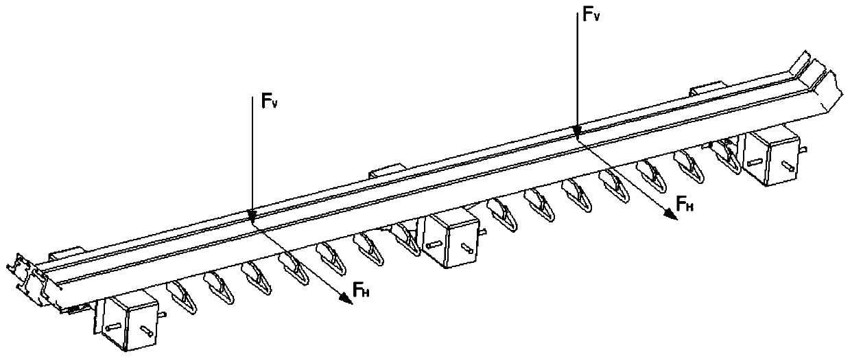
[0043] A high-strength anti-fatigue modulus bridge expansion device, such as Figure 10 , Figure 11 , Figure 12 , Figure 13 and Figure 14 As shown, including the roadway displacement box 1, side beams 2 are respectively arranged on both sides of the roadway displacement box 1, and several anchor plate weldments 3 are evenly distributed on the outer side wall of the side beam 2, and the two side beams 2 A single or multiple middle beams 4 are arranged in the middle, and a crossbeam 5 perpendicular to the middle beam 4 is horizontally pierced in the roadway displacement box 1, and the upper part of the externally expanded special-shaped support pad is welded and connected between the middle beam 4 and the crossbeam 5 6. The upper part of the externally expanded special-shaped support pad 6 is fixed with a center beam support rib 7 on both sides along the length direction of the center beam 4. The top edge of the center beam support rib 7 is welded to the center beam 4, an...

specific Embodiment 2

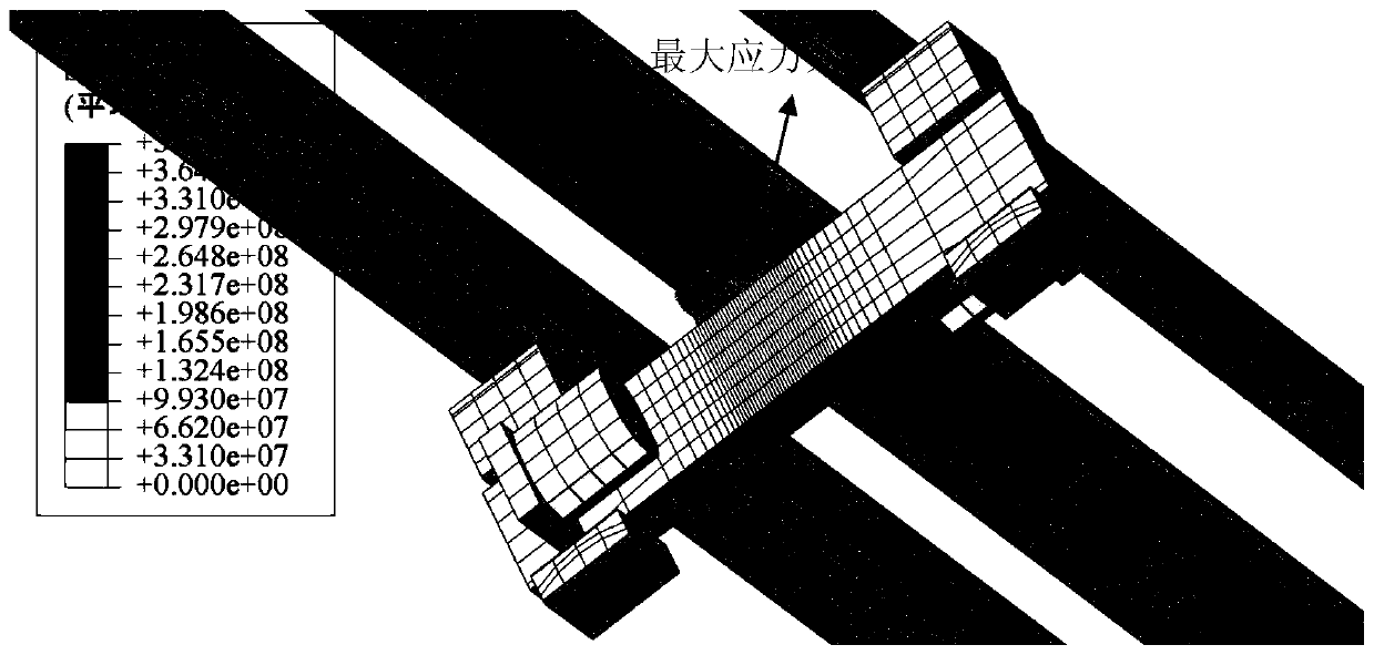
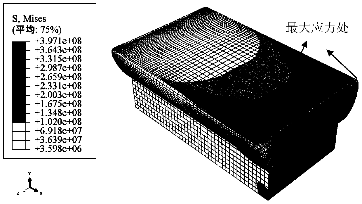
[0050] If the construction space for the welding operation is sufficient, two middle beam support ribs 7 with a thickness of 16mm can be respectively set on both sides of the upper externally expanded special-shaped support pad 6, such as Figure 15 , Figure 16 , Figure 17 and Figure 18 Shown, all the other are with above-mentioned concrete example one. like Figure 8 and Figure 9 As shown, after the finite element analysis, it is found that the new maximum stress position of the weld is at the bottom of the junction between the diagonal brace and the weld, which reflects the force transmission effect of the diagonal brace. At this time, the maximum stress is 175MPa, which can meet the two indicators of yield strength and pulsation strength better than Example 1, and the structural strength and fatigue resistance performance are further improved. The process is also more complicated.

[0051] The present invention is not limited to the center sill support ribs 7 with...


PUM


Abstract

The invention discloses a high-strength anti-fatigue modular bridge expansion device and a construction method. The high-strength anti-fatigue modular bridge expansion device comprises a roadway displacement box; boundary beams are correspondingly arranged on the two sides of the roadway displacement box; a plurality of anchor plate welding pieces are uniformly distributed on the external side walls of the boundary beams; one or multiple center sills are arranged between the two boundary beams; cross beams perpendicular to the center sills horizontally penetrate into the roadway displacement box; the high-strength anti-fatigue modular bridge expansion device is characterized in that upper expanded special supporting cushion blocks are welded and connected between the center sills and the cross beams; at least one center sill supporting rib plate is fixedly arranged on the two sides, in the length directions of the center sills, of the upper expanded special supporting cushion blocks; the top edges of the center sill supporting rib plates are welded to the center sills; and the side edges of the center sill supporting rib plates are welded and connected to the cross beams. In the construction process, the upper surfaces of the upper expanded special supporting cushion blocks are connected with the center sills in a full-length welding manner. The high-strength anti-fatigue modular bridge expansion device has the advantage that strength and anti-fatigue requirements of national regulations on the bridge expansion device can be satisfied through calculation.

Description

technical field [0001] The invention relates to the field of bridge connecting parts and construction, in particular to a high-strength anti-fatigue modulus bridge expansion device and a construction method. Background technique [0002] In order to adapt to changes in the length of the bridge structure caused by factors such as thermal expansion and cold contraction, expansion devices need to be installed at both ends of the bridge, and the modular expansion device is a commonly used bridge expansion joint device. like figure 1 As shown, the modular expansion device includes structures such as side beams, middle beams, and cross beams. By adjusting the gap width between side beams and beams, and between beams (in the case of multiple beams), it can adapt to the expansion of the bridge structure. shrink. The modular bridge expansion joint device is simple in structure and convenient in construction, and is widely used in engineering. However, due to the expansion joints p...

Claims


Application Information

Patent Timeline
Patent Type & Authority Applications(China)
IPC IPC(8): E01D19/06
CPCE01D19/062
Inventor 韩凌霞丁勇俞丹波于静远商良荣吕建华徐速丁健
Owner NINGBO UNIV
Why Eureka
Try Eureka