Detachable prefabricated assembly type steel-concrete composite beam and construction method thereof

A technology of prefabricated assembly and composite beams, applied to structural elements, building components, and long-strip structural components for load-bearing, etc., can solve problems such as difficult control of welding quality, complicated on-site construction, complex disassembly and repair, etc., and achieve high resistance Shearing, improving construction efficiency, high ductility and energy dissipation performance

Pending Publication Date: 2019-08-02
XIANGTAN UNIV
View PDF8 Cites 5 Cited by
  • Summary
  • Abstract
  • Description
  • Claims
  • Application Information

AI Technical Summary

Problems solved by technology

At present, most of the connections between shear connectors and steel beams in composite structures are welded. This method is complex on-site construc

Method used


Image

  • Detachable prefabricated assembly type steel-concrete composite beam and construction method thereof
  • Detachable prefabricated assembly type steel-concrete composite beam and construction method thereof
  • Detachable prefabricated assembly type steel-concrete composite beam and construction method thereof

Examples


Embodiment 1

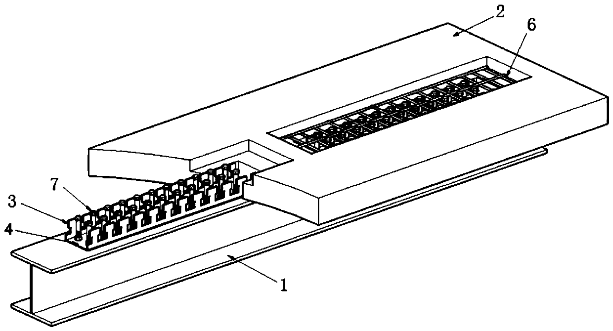
[0076] Such as figure 1 As shown, a detachable prefabricated steel-concrete composite beam includes a steel beam 1, a concrete slab 2, a concave-convex steel plate connector 3, and a spliced ​​steel plate 4. Steel beam 1 is I-shaped steel or rectangular steel structure. Splicing steel plate 4 is arranged on the upper surface of steel beam 1. The two concave-convex steel plate connectors 3 are arranged on both sides of the spliced ​​steel plate 4, and the two concave-convex steel plate connectors 3 and the spliced ​​steel plate 4 form a "U" structure. A T-shaped shear notch 201 is provided in the middle of the concrete slab 2 . A concrete slab 2 is placed above the steel beam 1 . The two concave-convex steel plate connectors 3 and the spliced ​​steel plate 4 form a "U"-shaped structure located in the T-shaped shear notch 201 of the concrete plate 2. In the T-shaped shear notch 201 of the concrete slab 2, the concrete layer is poured after the shear groove is poured.

[007...

Embodiment 2

[0079] Such as figure 1 , Figure 7 As shown, embodiment 1 is repeated, except that the composite beam also includes a lower reinforcement mesh 5 . The lower layer of steel mesh 5 is arranged in the T-shaped shear notch 201 of the concrete slab 2, and the concave-convex steel plate connector 3 passes through the lower layer of steel mesh 5, and the lower layer of steel mesh 5 contacts with the bottom of the concave-convex steel plate connector 3.

[0080] The composite beam also includes an upper reinforcement mesh 6 . The upper steel mesh 6 is set in the T-shaped shear notch 201 of the concrete slab 2, and the upper steel mesh 6 is located above the concave-convex steel plate connector 3, and the bottom surface of the upper layer steel mesh 6 is in contact with the top of the concave-convex steel plate connector 3.

[0081] The connection effect between the concave-convex steel plate connector and the post-cast concrete layer of the shear groove in the T-shaped shear notch ...

Embodiment 3

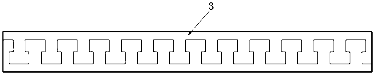
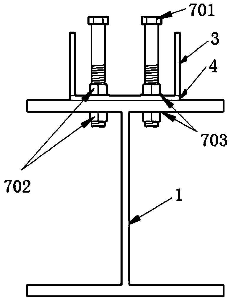
[0083] Such as figure 1 , image 3 As shown, Example 1 is repeated, and the upper surface of the steel beam 1 is provided with a steel beam connection hole 101 . The steel beam connection hole 101 runs through the upper surface of the steel beam 1 . The spliced ​​steel plate 4 is provided with a steel plate connection hole 401 . The steel plate connection hole 401 runs through the spliced ​​steel plate 4 . The spliced ​​steel plate 4 is connected to the steel beam 1 through the steel beam connecting hole 101, the steel plate connecting hole 401 and bolts.


PUM

PropertyMeasurementUnit
Widthaaaaaaaaaa

Abstract

The invention provides a detachable prefabricated assembly type steel-concrete composite beam. The composite beam comprises a steel beam, a concrete slab, concave-convex steel board connecting piecesand a splicing steel board, the steel beam is of an I-shaped steel or rectangular steel structure, and the splicing steel board is arranged on the upper surface of the steel beam. The two concave-convex steel board connecting pieces are arranged on the two sides of the splicing steel board, and the two concave-convex steel board connecting pieces and the splicing steel board form a U-shaped structure. A T-shaped shear notch is formed in the middle of the concrete slab, the concrete slab is arranged above the steel beam, and the U-shaped structure formed by the two concave-convex steel board connecting pieces and the splicing steel board is located in the T-shaped shear notch of the concrete slab, and a shear groove post-pouring concrete layer is poured in the T-shaped shear groove openingof the concrete slab. The detachable prefabricated assembly type steel-concrete composite beam is convenient to construct, high in bearing capacity, high in shear capacity of connection between the steel beam and the prefabricated reinforced concrete slab, high in uplift bearing capacity, good in energy consumption performance and convenient to disassemble.

Description

technical field [0001] The invention relates to a composite structural beam, in particular to an assembled steel-concrete composite structural beam, which belongs to the technical field of structural engineering steel structures. Background technique [0002] Composite structures are widely used in roads, bridges and building neighborhoods due to their advantages of convenient construction and reasonable utilization of material properties. Prefabricated structural systems are gradually being widely used and developed in engineering practice. Prefabricated structural systems are used in composite structures. Zhongneng can improve labor productivity, speed up construction, reduce project cost and improve project quality. At present, there are two construction methods for concrete slabs in steel-concrete composite structures: prefabrication and cast-in-place. The prefabrication method can greatly reduce on-site wet work, not only improve production efficiency, but also be envir...

Claims


Application Information

Patent Timeline
IPC IPC(8): E04C3/293E04C3/294
CPCE04C3/293E04C3/294
Inventor 陈俊陈超汪威陈绪林许福杨才千龙士国王开吴蒙彭月刘雨晴刘哲胥卉
Owner XIANGTAN UNIV
Why Eureka
Try Eureka