Electric pushing rod structure

A technology of electric push rods and transmission shafts, which is applied in the direction of electric components, electrical components, electromechanical devices, etc., can solve the problems of large volume products, small application range, and increased volume, and achieve low cost, convenient adjustment, and reduction The effect of small volume

Pending Publication Date: 2019-08-02
宁波市奉化强敏龙森电器有限公司
View PDF0 Cites 1 Cited by
  • Summary
  • Abstract
  • Description
  • Claims
  • Application Information

AI Technical Summary

Problems solved by technology

[0002] The electric push rod, also known as the linear drive, is an electric drive device that converts the rotational motion of the motor into the linear reciprocating motion of the push rod. It can be used as an execution machine in various simple or complex processes to achieve long-distance control, centralized control or automatic control; it is widely used as a motion drive unit in household appliances, kitchen utensils, medical equipment, automobiles and other industries; It is necessary to increase the diameter of the turbine, and the ensuing problem is that the volume is large, and the electric push rod cannot be applied to some products with small space, and the scope of application is small. In addition, in order to match the reduction ratio, the drive motor must be replaced. The increase in power will inevitably lead to a further increase in volume; at the same time, the enlargement of the turbine, the increase in the volume of the electric push rod and the increase in the power of the drive motor will all result in more materials and high costs for the product; in addition, the existing electric push rod The driving screw only contains a single thread, so the transmission friction between the screw nut and the driving screw is extremely large. When the driving motor fails or is in a power-off state, the screw nut will always stop at the original position. Pushing and pulling the screw nut manually does not work, and needs to be further improved

Method used


Image

  • Electric pushing rod structure
  • Electric pushing rod structure
  • Electric pushing rod structure

Examples


Embodiment Construction

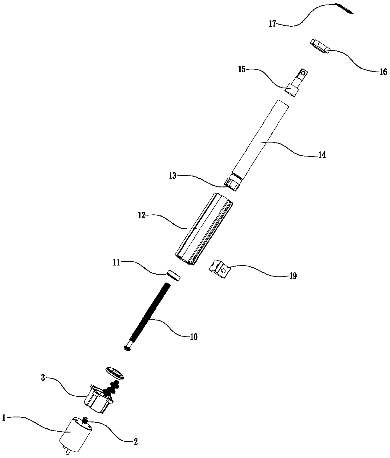
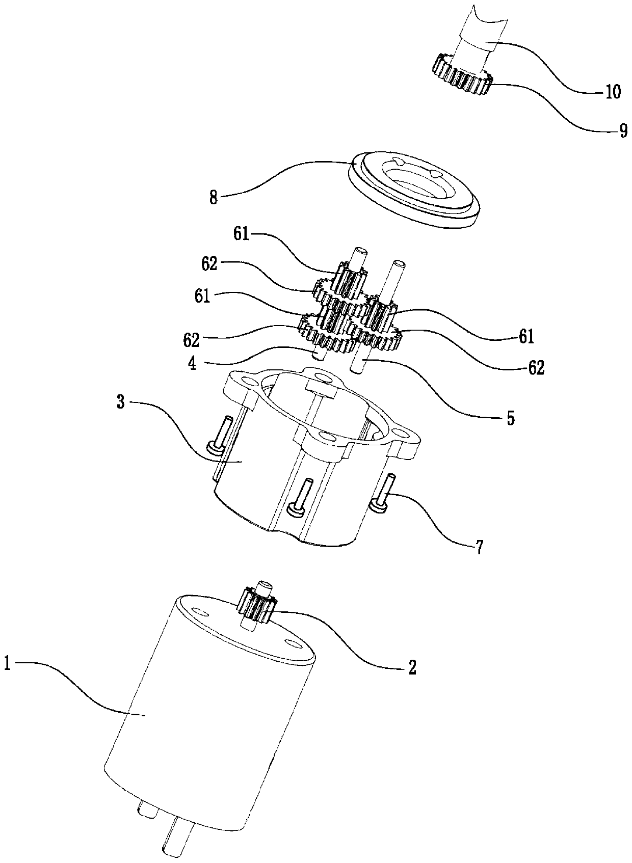
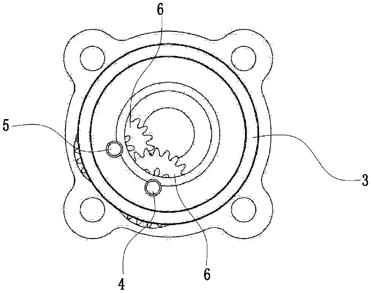
[0018] Such as Figure 1~4 As shown, an electric push rod structure includes a motor 1, a driving gear 2, a reduction box 3, a bolt 7, a first transmission shaft 4, a second transmission shaft 5, a transmission gear 6, a case cover 8, an output gear 9, a drive The screw 10 and the executive assembly, the reduction box 3 are fixed on the outer side of the rotating end of the motor 1, and the rotating shaft of the motor 1 is inserted into the inside of the reduction box 3; the outer end of the reduction box 3 is embedded with a box cover 8, and the driving gear 2 is sleeved and fixed On the rotating shaft of the motor 1 and located inside the reduction box 3; the inside of the reduction box 3 is provided with two eccentrically distributed first transmission shafts 4 and second transmission shafts 5, and the first transmission shaft 4 is sleeved with two Rotatable transmission gear 6, the second transmission shaft 5 is sleeved with a rotatable transmission gear 6, one transmissio...


PUM


Abstract

The invention relates to an electric pushing rod structure. The electric pushing rod structure comprises a motor, a drive gear, a reduction gearbox, bolts, a first transmission shaft, a second transmission shaft, variable gears, a box cover, an output gear, a drive lead screw and an execution assembly. The speed reduction is carried out with the adoption of a mode that gears arranged eccentricallyare mutually superposed in a transmission manner, so that the size is reduced substantially, and the application scope is expanded; adjustment on the reduction ratio is achieved by increasing or reducing the number of the variable gears, so that the operation is easy; simultaneously, a plurality of threads are formed in the drive lead screw, and the transmission friction force between the drive lead screw and a lead screw nut is reduced, so that the application scope is further expanded; and with the adoption of a T-shaped block, the electric pushing rod structure can be applied in the fieldthat a straight line is combined with turning drive, the application scope is expanded again, and the fixing position of the T-shaped block is adjustable, so that the turning radius is adjustable, andthe adjustment is facilitated.

Description

technical field [0001] The invention relates to an electric push rod structure. Background technique [0002] The electric push rod, also known as the linear drive, is an electric drive device that converts the rotational motion of the motor into the linear reciprocating motion of the push rod. It can be used as an execution machine in various simple or complex processes to achieve long-distance control, centralized control or automatic control; it is widely used as a motion drive unit in household appliances, kitchen utensils, medical equipment, automobiles and other industries; It is necessary to increase the diameter of the turbine, and the ensuing problem is that the volume is large, and the electric push rod cannot be applied to some products with small space, and the scope of application is small. In addition, in order to match the reduction ratio, the drive motor must be replaced. The increase in power will inevitably lead to a further increase in volume; at the same...

Claims


Application Information

Patent Timeline
Patent Type & Authority Applications(China)
IPC IPC(8): F16H57/023F16H25/20H02K7/116
CPCF16H25/20F16H57/023F16H2025/2075H02K7/116
Inventor 王强
Owner 宁波市奉化强敏龙森电器有限公司
Why Eureka
Try Eureka