Friction experiment device for friction performance test of cutting tool coating

A friction performance and experimental device technology, applied in the direction of measuring devices, testing wear resistance, strength characteristics, etc., can solve the problems of difficult management of devices, limited friction duration, inability to provide tribological phenomena, etc., to achieve non-deformation and high rigidity , to achieve the effect of heavy load friction experiment

Pending Publication Date: 2019-08-02
QINGDAO TECHNOLOGICAL UNIVERSITY
View PDF0 Cites 5 Cited by
  • Summary
  • Abstract
  • Description
  • Claims
  • Application Information

AI Technical Summary

Problems solved by technology

Simulated higher contact pressures (up to 3 GPa) at high sliding velocities (up to 400 m / min) designed by Zemzemi et al. showed high efficiency in providing relevant coefficients of friction, however, their invented device was very difficult to manage and the workpiece Very long and expensive to manufacture
In addition, the friction duration of this device is very limited (approximately 10 seconds), making it impossible to perform long-term wear tests
Hedenqvist et al. proposed a device with a pin of cylindrical geometry rubbing against a rotating surface that could generate sufficient velocity (hundreds of m / min) and be tested for long periods of time, but could not provide sufficient local pressure (approx. 15MPa) to simulate the tribological phenomena that occur during machining
[0005] It can be seen that in the prior art, there is no device that can provide sufficient contact pressure and have a long test time for testing the cutting friction force of the tool

Method used


Image

  • Friction experiment device for friction performance test of cutting tool coating
  • Friction experiment device for friction performance test of cutting tool coating
  • Friction experiment device for friction performance test of cutting tool coating

Examples


Embodiment Construction

[0044] The present invention is described in detail below in conjunction with accompanying drawing description:

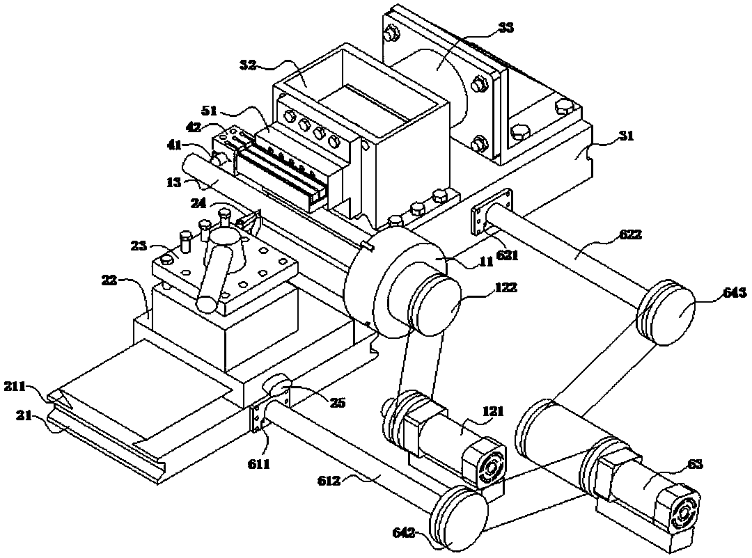
[0045] Such as figure 1As shown, the present invention includes a rotary fixing mechanism for providing rotational power for the columnar workpiece 13, a cutting mechanism for cutting the surface of the columnar workpiece 13, a pressure regulating mechanism for providing and adjusting the experimental pressure, and a friction mechanism for friction experiments. , a data collection mechanism for data collection and analysis, and a feed action mechanism for providing relative feed movement of the columnar workpiece 13;

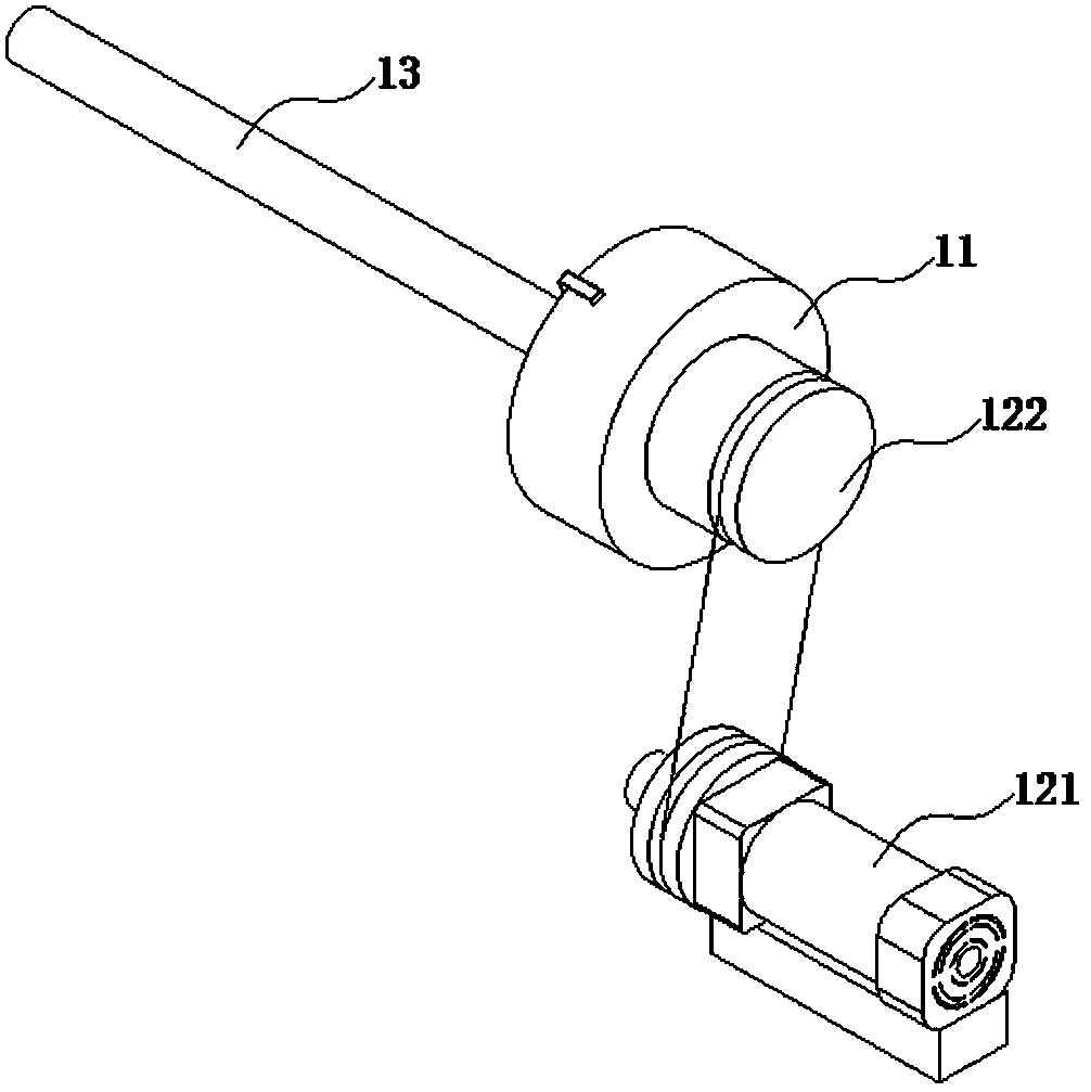
[0046] Such as figure 2 As shown, the rotation fixing mechanism includes a three-jaw chuck 11, a first driving device for driving the three-jaw chuck 11 to rotate in a circumferential direction, and a cylindrical workpiece 13 fixedly installed on the three-jaw chuck 11 and used for friction experiments; The first driving device includes a first dr...


PUM


Abstract

The invention relates to the technical field of friction wear test and especially relates to a friction experiment device for friction performance test of a cutting tool coating. The friction experiment device comprises a rotary fixation mechanism, a cutting mechanism, a feed action mechanism, a friction mechanism, a data acquisition mechanism and a pressure regulating mechanism. The rotary fixation mechanism comprises a three-jaw chuck, a first drive device for driving the three-jaw chuck to rotate circumferentially, and a cylindrical workpiece fixedly arranged on a three-jaw chuck and used for friction test. The cutting mechanism comprises a base, a cutting base, a turret mounted on the cutting base and a cutting tool mounted on the turret. The cutting tool is located beside the cylindrical workpiece. The friction experiment device can ensure having enough contact pressure and meanwhile, having longer test time.

Description

technical field [0001] The invention relates to the technical field of friction and wear testing, in particular to a friction experiment device for testing the friction performance of tool coatings. Background technique [0002] In the context of global competition, in order to improve the efficiency of production and processing, the current industry usually adopts very high cutting speed for the processing of cutting tools. High mechanical stress and temperature are generated, which leads to excessive wear and even premature failure of the tool during production and processing, and ultimately leads to a high scrap rate. Therefore, in order to prevent such a situation from happening, it is necessary for us to establish an accurate simulation of the cutting process to determine the best cutting conditions from the aspects of tool material, tool geometry and coating, etc., so as to maintain a high machining operation productivity and reduce scrap Rate. [0003] In order to s...

Claims


Application Information

Patent Timeline
Patent Type & Authority Applications(China)
IPC IPC(8): G01N3/56G01N3/02
CPCG01N3/02G01N3/56G01N2203/0278
Inventor 姜芙林杨发展王玉玲李成
Owner QINGDAO TECHNOLOGICAL UNIVERSITY
Why Eureka
Try Eureka