
Anti-static die-cutting machine for self-adhesive labels

An anti-static, die-cutting machine technology, applied in the direction of static electricity, electrical components, metal processing, etc., can solve the problems of affecting the normal use of labels, disordered label printing pressure, easy to generate static electricity, etc., and achieve the effect of increasing the range of current generation

Active Publication Date: 2019-08-06
德州金彩精密机械制造有限公司
View PDF9 Cites 7 Cited by
  • Summary
  • Abstract
  • Description
  • Claims
  • Application Information

AI Technical Summary

Problems solved by technology

[0003] Aiming at the deficiencies in the prior art, the purpose of the present invention is to provide an anti-static die-cutting machine for self-adhesive labels to solve the problem in the prior art that when the label is die-cut, because the surface of the label is made of film material, it will Contact and dry environment in the workshop, it is easy to generate static electricity, so that when the die-cutting board is in contact with the label, it will be picked up by it due to static electricity, resulting in misalignment of the label and disordered printing pressure on the whole label. Printing and embossing labels will cause the labels to be cut randomly, resulting in waste of paper. At the same time, static electricity is easy to absorb with dust, so that when the die-cutting machine is in contact with the label, uneven holes will be formed on the surface under the action of static electricity, dust, and gravity. , thus affecting the normal use of the label

Method used


Image

  • Anti-static die-cutting machine for self-adhesive labels
  • Anti-static die-cutting machine for self-adhesive labels
  • Anti-static die-cutting machine for self-adhesive labels

Examples


Embodiment Construction

[0025] In order to make the technical means, creative features, goals and effects achieved by the present invention easy to understand, the present invention will be further described below in conjunction with specific embodiments.

[0026] Such as Figure 1-Figure 6 As shown, the present invention provides a technical scheme of self-adhesive label anti-static die-cutting machine:

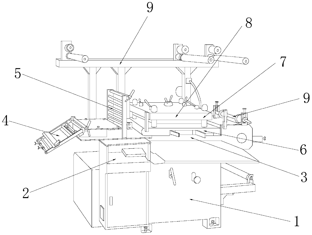
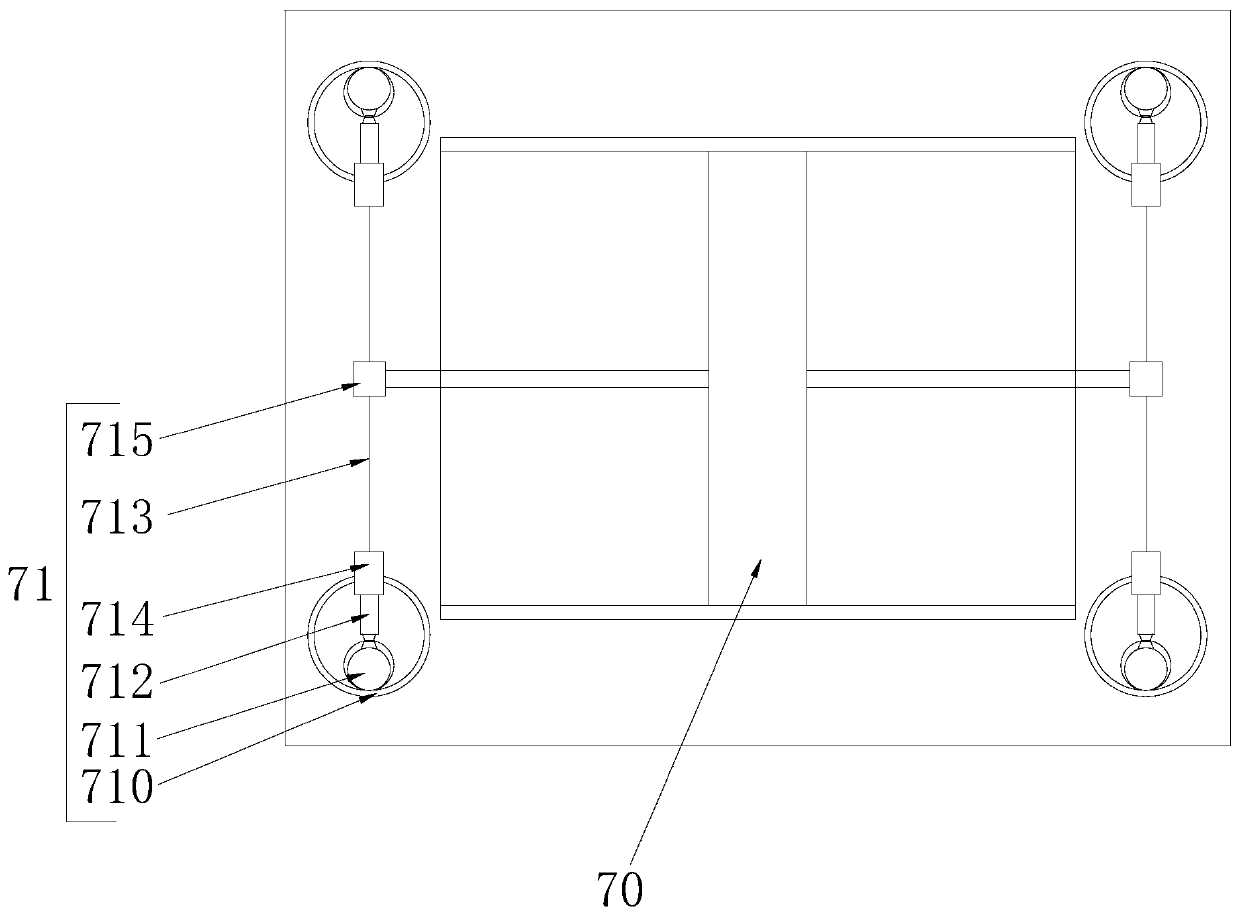
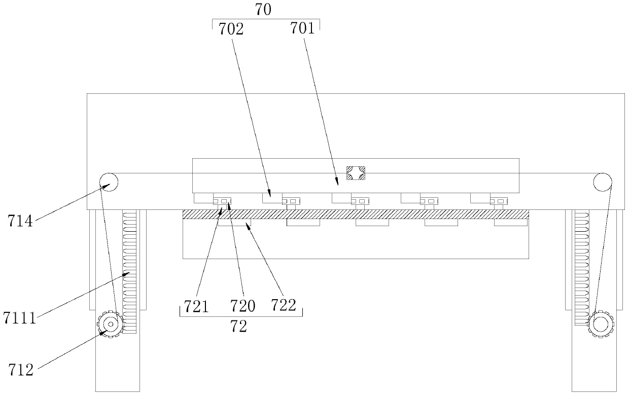
[0027] Such as figure 1 - As shown in convex 3, an anti-static die-cutting machine for self-adhesive labels, its structure includes an equipment power box 1, an equipment console 2, a workbench 3, a feeding frame 4, a laminating frame 5, a fixed template 6, an anti-static Electrostatic device 7, movable die-cutting board 8, feeding rack 9, said equipment console 2 is installed on the left side of equipment power box 1 and connected by electric welding, said workbench 3 is installed on the upper surface of equipment power box 1, said The feeding frame 4 is installed on the left side of the upper ...


PUM


Abstract

The invention discloses an anti-static die-cutting machine for self-adhesive labels. The anti-static die-cutting machine for the self-adhesive labels structurally comprises an equipment power box, anequipment console, a workbench, a charge frame, a fitting frame, a fixed die plate, an anti-static device, a movable die-cutting plate and a pouring frame. The anti-static die-cutting machine for theself-adhesive labels has the following beneficial effects: the current generation range of a high-voltage generator is effectively expanded by virtue of the expanded state of an elastic folding platewhen a transmission mechanism moves downwards to be close to the labels, so that disordered overall labels and staggered coining caused due to that the labels carry out up-down movement along with themovable die-cutting plate because films on the own surfaces of the labels generate static electricity in a dry environment and under metal collision friction when the labels make contact with the movable die-cutting plate, are avoided; and meanwhile, 360-degree sweeping is carried out on dust covering the surface of the lower part of the movable die-cutting plate through a dust sweeping mechanism, so that uneven traces formed on the surfaces of the labels under the downward gravity effect due to dust covering the surfaces during coining, because dust covers the surface of the movable die-cutting plate and is easily mutually adsorbed with electrons, are avoided.

Description

technical field [0001] The invention relates to the field of self-adhesive label die-cutting, more precisely, an anti-static die-cutting machine for self-adhesive labels. Background technique [0002] With the growth of e-commerce day by day, online shopping is becoming more and more popular, and the workload of the logistics industry is also increasing day by day. From the previous manual filling of orders to today's electronic orders, it is becoming more and more important. Perfect, the electronic list is mainly based on self-adhesive labels, because the labels are mainly made of paper, film or other special materials, and the back is coated with adhesive, and the silicon-coated protective paper is used as the backing paper. A conforming material, and this type of label can be used after a series of processing procedures such as printing and die-cutting in the production process of the finished label. Die-cutting of different sizes and shapes, but at present, when this ki...

Claims


Application Information

Patent Timeline
IPC IPC(8): B26F1/38B26F1/44B26D7/08H05F3/04
CPCB26D7/08B26D7/088B26F1/38B26F1/44B26F2001/4418H05F3/04
Inventor 张秋达曾小真张智超
Owner 德州金彩精密机械制造有限公司
Learn More